Hydraulic Power Units (HPUs) are the heart of many industrial systems, and optimising their hydraulic fittings is crucial for performance, cost, and reliability. Traditionally, engineers manually select hoses, tubes, and adapters, often using personal experience to guess optimal routing and parts. This manual process is time consuming and prone to errors; an oversight in the Bill of Materials (BOM) or a misjudged hose length, for instance, can lead to costly rework. AI driven optimisation addresses these challenges by automating and enhancing the design workflow. By leveraging Artificial Intelligence, engineers can speed up design iterations, reduce human error, and ensure more consistent, high quality outcomes.
Optimising hydraulic fittings with AI isn’t just about saving time; it directly improves build quality and cost efficiency. AI algorithms can evaluate countless routing possibilities quickly, often finding configurations that use fewer fittings or shorter hose lengths than a manual approach might. The result is a BOM with fewer unnecessary parts and optimal lengths, which reduces material costs and minimises potential leak points. In fact, AI assisted design can automatically generate detailed layouts with high accuracy and zero drafting errors. This leads to higher build quality: properly routed hoses that respect bend radii, well chosen connectors that avoid leaks, and an overall cleaner HPU assembly. Engineers and project managers benefit from more predictable builds, resulting in faster assembly times, fewer maintenance issues, and a smoother commissioning process.
AI plays a transformational role by acting as a smart “co pilot” in the design process. Modern Large Language Models (LLMs) and associated AI tools can parse design requirements, check them against extensive databases of components and rules, and then suggest the best fitting solutions. For example, AI can cross reference a hydraulic schematic with a supplier’s catalogue in seconds, ensuring each fitting meets pressure and size specifications while also checking availability and price in real time. The AI doesn’t replace the engineer; rather, it augments their capabilities. Engineers can focus on high level decision making and creative problem solving, while the AI handles repetitive and data intensive tasks, such as comparing dozens of elbow versus tee fitting options or computing whether a hose violates its minimum bend radius. In summary, embracing an AI driven workflow for hydraulic fitting optimisation leads to greater productivity through faster design and quoting, lower costs, and improved build quality of HPUs, which is a win win for engineering teams and their clients.
Implementation Phases
Implementing an AI driven optimisation workflow involves several phases. It’s wise to approach this step by step: beginning with developing the core system, then integrating it into daily workflows, piloting it on real projects, and finally rolling it out fully with training and governance. We’ll break down each phase in detail.
Phase 1: System Development
In the development phase, the goal is to build the foundation of the AI driven system. This includes setting up data pipelines from CAD, consolidating relevant datasets (like part catalogues and design rules), and deploying the AI models that will drive the recommendations.
- BOM and Spatial Data Extraction from SolidWorks: The journey begins in the CAD environment. We need a way to get the necessary information out of SolidWorks, which is the CAD platform for our HPU designs. Specifically, we want to extract the Bill of Materials (BOM) of the assembly and spatial data about the component layout (for example, port locations or distances between connection points). SolidWorks provides an API for this, so one can write a VBA macro or a C# add in to traverse the assembly and pull out BOM information. In practice, the macro would list all existing hoses, pipes, fittings, etc., along with their parameters (sizes, lengths) and could also output a structured file (XML or CSV) for the AI to ingest. Spatial data might be obtained by exporting coordinates or using a naming convention, for example, tags on parts indicating which port connects to which. Automating this extraction is crucial, as it ensures the AI always works with up to date design data without manual transcription errors. For example, a macro can save the BOM to an XML file in seconds; doing this by hand risks missing a part or mistyping a part number. By having BOM and geometry data in a computer readable format, we set the stage for the AI to analyse the current design state comprehensively.
- Integrating Supplier Catalogues and Real Time Data: With the design data in hand, the next step is to give the AI “knowledge” of available components. This means integrating supplier catalogues, which are databases of hydraulic fittings, hoses, and related components, including their specifications (thread sizes, pressure ratings, dimensions) and ideally real time information like pricing and stock levels. Traditionally, BOM costing and part selection relied on static data that might be updated only periodically, which posed risks as prices and availability change frequently. In our AI system, we plan to link to live data. Many suppliers offer APIs or data feeds for their products. By connecting these to a database (or directly querying them when needed), the AI can check current prices and lead times for any recommended part. This real time aspect is invaluable. For instance, if a particular elbow fitting is out of stock or has a 6 week lead time, the AI could suggest a readily available alternative equivalent. Modern BOM tools emphasise this capability, as providing up to the minute insights on component availability helps avoid design decisions that would cause procurement delays. The AI can even go further by considering bulk pricing breaks or flagging if a part is nearing obsolescence, ensuring the optimised BOM is not only technically sound but also procurement friendly.
- Engineering Constraints Database: Optimisation must work within the bounds of engineering reality. This is where an engineering constraints database comes into play. We compile a knowledge base of all relevant design rules and constraints specific to hydraulic assemblies. Examples include minimum bend radius for hoses (depending on hose diameter and construction), minimum straight length needed before a tube can be flared or bent, thread engagement standards, and torque clearance requirements for fittings. By encoding these rules, the AI can avoid suggesting impractical solutions. For instance, if the AI considers replacing a curved hose with a straight tube plus bends, it must know the bend radius limits so that the tube routing is feasible without kinking. (Recall that each hose has a manufacturer specified minimum bend radius, which is the tightest curve it can handle without damage.) Similarly, when using flared tube fittings, there must be enough straight length for the flaring tool and the flare nut. The database might specify a minimum length, for example, 50 mm of straight tube between a bend and a flare. All these rules, whether derived from manufacturer data, industry standards, or company experience, are stored in a structured form (perhaps as JSON or in a small SQL database) that the AI and its retrieval system can query. This ensures that any optimisation the AI proposes already respects the basic engineering feasibility constraints before an engineer ever sees it.
- Local LLM Deployment via Ollama (e.g. DeepSeek): At the core of the system is the AI engine, which will likely be a Large Language Model (LLM) capable of understanding prompts and generating recommendations. We choose to deploy a local LLM, which means it runs on our hardware (a workstation or server) rather than calling an external cloud service. This is made feasible by tools like Ollama, which is a runtime for running LLMs locally, and by advanced open source models such as DeepSeek R1. Running the model locally has several advantages: privacy, as sensitive design data never leaves your network; speed, because there’s no network latency when inference happens on a GPU/CPU right next to the data; and cost, with no API fees for each query. DeepSeek, for example, is an open source 67B parameter LLM known for strong reasoning in technical tasks. Because it’s open, we have full control; we can even fine tune it or modify its behaviour as needed. By deploying it via Ollama, we can download the model files (the “modelfile”) and run inference on premises. Many organisations prefer this setup for compliance reasons, as designs can be proprietary and keeping AI on site avoids any data exposure risk. In practical terms, setting up Ollama with DeepSeek might involve pulling the model (ollama pull deepseek) and then running an API server on the local machine that the rest of our pipeline can query. The LLM will be the brain that takes all our inputs (BOM, spatial data, constraints, etc.) and generates intelligent fitting and routing suggestions.
- Using RAG (Retrieval Augmented Generation) for Specs, Constraints, and History: Large Language Models are powerful but they don’t inherently “know” specifics about your project or company rules unless you tell them. This is where Retrieval Augmented Generation (RAG) comes in. RAG is a technique where the LLM is provided with relevant external information from a knowledge base every time you query it. In our case, when we ask the LLM to optimise the fittings, we will supply it with documents from our vector database that contain component specifications (from the supplier catalogue), engineering constraints (from our rules DB), and possibly historical design data or past decisions. The mechanism works like this: first, any relevant text, such as datasheets, rules, or past project BOMs, is converted into vector embeddings and stored in a vector database for semantic search. When we query the AI, for example, with “Optimise the hose routing between the pump outlet and manifold inlet”, the system will use an embedding model to encode that query and find the most relevant chunks of data, like the spec sheet for the pump’s outlet port and the manifold’s port, or bend radius rules for hoses of that size, etc. These chunks are then appended to the LLM’s prompt, so the model can draw on up to date facts rather than just its base training. This prevents hallucinations and ensures accuracy. Essentially, RAG gives the LLM a real time library; it connects the question to the database and augments the prompt with relevant data for better answers. We strongly benefit from RAG here because the AI needs precise numbers (like thread sizes and pressure ratings) and rules (such as “hose X can’t bend under radius Y”) to make valid recommendations. By using RAG, our LLM remains lightweight and generic, while the domain specific knowledge lives in the retrievable documents. It’s a flexible approach: if a new standard or component is introduced, we just add it to the knowledge base, and it’s immediately accessible to the AI without retraining the model.
- Workflow Orchestration with n8n: Building the system involves stitching together multiple tools and steps, such as extraction from SolidWorks, database queries, and AI calls. To handle this flow, we recommend using n8n, a workflow automation tool. n8n is a free, open source platform for automating processes, allowing you to connect various services and APIs in a visual workflow. Think of it as the glue that holds our pipeline together. An n8n workflow can be triggered, perhaps by an engineer clicking a button after finishing a rough design. Then one node runs the SolidWorks BOM extraction macro, the next node might call a script to push that BOM data into a database or directly query the supplier API for part information, another node sends all this context to the LLM (via an HTTP request to the local Ollama API), and finally other nodes process the LLM’s response, perhaps by emailing a report or feeding back into CAD. Using n8n has several benefits for our implementation: it’s visual and easier to maintain than custom scripts; it has built in integrations (for example, it could have a node for HTTP requests or a node for database queries); and it supports conditional logic and error handling. This means we can create a robust data pipeline without heavy bespoke coding, and we can adjust it easily; for example, if we add a new data source, we just drag a new node into the workflow. In summary, n8n orchestrates our AI workflow, ensuring the right data flows to the right components at the right time. This approach aligns with modern data pipeline practices, where automation tools handle data extraction, transformation, and routing reliably, so engineers can trust that the AI suggestions are based on the latest design state and supplier information.
By the end of the System Development phase, we will have a working “engine” for AI driven optimisation: SolidWorks can output design data, our system holds knowledge about parts and rules, an LLM (DeepSeek) is running locally to generate suggestions, and n8n ties everything together. The next step is making this engine a seamless part of the engineer’s everyday workflow.
Phase 2: Workflow Integration
Developing a powerful AI system is great, but to truly reap its benefits, it must integrate smoothly into the engineer’s daily tools and processes. In this phase, we focus on embedding the AI recommendations back into the CAD workflow and making it easy for engineers to act on AI output. We also ensure the outputs are in a useful form for downstream processes like procurement.
- Automating BOM Extraction in SolidWorks: First, we operationalise the BOM extraction. Instead of an engineer running a macro manually each time, we aim to automate this. One method is to create a SolidWorks add in (in C#) that adds a new toolbar button or menu item, for example, “AI Optimise Fittings”. When clicked, this add in can internally trigger the macro or API calls to gather BOM data from the open assembly. SolidWorks’ API allows enumeration of the assembly tree and collection of component data, like part numbers and custom properties. The add in could even directly invoke our n8n workflow via a REST call, sending the BOM data payload. The goal is to make extraction a one click or automatic process, rather than a multi step manual export. By doing so, we ensure that engineers use the AI consistently (no one skips it because it’s too much hassle) and that the data the AI sees is always current. This automation also frees engineers from the tedium of data preparation, meaning no more copying BOMs to Excel and cleaning them up, as the system handles it instantly, every time.
- Injecting AI Generated BOM and Routing Recommendations into SolidWorks: Once the AI (LLM) processes the data and comes up with suggestions, we need to present those suggestions to the engineer in the CAD context. There are a couple of ways to do this. A straightforward approach is to generate a report, perhaps an HTML or text report, that SolidWorks can display in a task pane or as a popup. This report would list recommended changes: for example, “Replace hose part #1234 (1000 mm) with hose part #5678 (800 mm) plus a 90° elbow fitting, to reduce slack and avoid a tight bend.” Another, more advanced, approach is to have the add in actually modify the CAD model: the SolidWorks API could insert the suggested new parts (fittings) into the assembly. There is API support for adding components and even mating them in position, although automatically routing a hose is complex. In practice, a semi automated approach might work best. The AI provides a list of recommended parts and perhaps a routing sketch or description, and then the engineer uses a CAD routing tool (SolidWorks Routing, for example) to implement it, guided by the suggestions. We could also colour code or flag areas in the model that the AI identified as problematic; for example, a hose with a bend radius violation could be highlighted in red. The injection should be as seamless as possible. If using an add in, it can cross reference the CAD model’s components. For example, if the AI says “add elbow fitting ABC at pump outlet”, the add in can locate the pump outlet in the model and place part ABC from the library at that location. This tight integration ensures the engineer doesn’t have to leave SolidWorks or do a lot of manual model editing to apply the AI’s optimisations. The result is an interactive CAD session where AI and engineer collaborate. The AI suggests and maybe auto adds parts, and the engineer reviews and accepts or tweaks the design accordingly.
- Generating Supplier Ready BOMs: With an optimised design and BOM in place, the next deliverable is often a BOM for procurement or quoting. The AI system can automate this as well. We want to output a supplier ready BOM, meaning a list of parts with the exact supplier part numbers, quantities, and possibly a breakdown by preferred vendor. Since our system already tapped into supplier catalogues for pricing and availability, we can compile that data. For example, if the optimised BOM includes 5 units of fitting X from Supplier A, and 3 hoses from Supplier B, the system can generate an Excel or PDF that is neatly organised per supplier, including each item’s description, part number, unit price, extended price, and lead time. In an AI assisted workflow, this step can be conversational or automated. (As an analogy, OpenBOM’s AI agent can, via a conversation, unify multiple BOMs and fill in vendor information; our system can do a similar consolidation automatically). The key benefit is speed and accuracy. Instead of an engineer manually collating a parts list and looking up each part’s details, the system does it in seconds, pulling the latest data. This not only saves time but improves accuracy, avoiding typos in part numbers or missed components, as the BOM is directly based on the CAD data and AI’s final output. The supplier ready BOM can also include annotations like highlighting long lead items or suggesting alternate parts for cost savings, giving purchasing teams a head start. Essentially, by the time the design is done, the BOM needed for ordering is already prepared automatically, dramatically compressing the design to procurement cycle.
- Live Availability and Lead Time Data: A powerful aspect of integrating AI with real time data is that engineers gain live insight into part availability. During the design phase (and definitely when reviewing the AI suggestions), the system can display which recommended parts are in stock or how long they’d take to arrive. For instance, the AI might suggest a particular hose assembly; if our integrated data shows that assembly is out of stock with a 4 week lead, the AI could flag this or propose a quicker alternative. This prevents nasty surprises later. Modern real time BOM tools emphasise this proactive approach; knowing stock levels across suppliers in real time means designers can make informed choices early. We can implement this by having the AI output not just “what” to use but also an availability note, since it can query the supplier data mid prompt. Alternatively, the n8n workflow after getting the AI’s BOM can call supplier APIs for each item and append availability info to the report. Imagine an engineer looking at a panel in SolidWorks that lists all required new parts with a green/yellow/red indicator next to each (green for in stock, red for backorder). This guides the engineer to perhaps tweak the design if necessary (maybe use a different fitting that’s readily available). It also impresses project managers, as they can immediately see if the design as conceived has any supply chain risks. By providing live availability and lead time data integrated in the design environment, we close the loop between design and supply chain. This makes the HPU build process much smoother, with fewer last minute design changes due to part unavailability, and more predictable project timelines.
Overall, the integration phase is about making the AI workflow a natural part of the design process in SolidWorks and beyond. Engineers should feel like they have a smart assistant at their side in the CAD software, giving suggestions and automating the grunt work, such as documentation and BOM compiling. When done right, this phase yields a system where using AI is as easy as a few clicks, and the outputs flow directly into the next steps (like procurement) with minimal human transcription. The groundwork from Phase 1 now comes to life in day to day usage.
Phase 3: Pilot & Validation
Before fully trusting an AI driven approach across all projects, it’s prudent to run a pilot programme. In this phase, we test the system on one or a few real HPU design projects, measure its performance against traditional methods, and gather feedback for improvements.
- Benchmarking Against Traditional Methods: The pilot should be set up as an experiment: compare how a project progresses with the AI workflow versus how it would have with the conventional process. For example, take a small HPU design that one team member will do using the AI suggestions, while another team member (or the same person, in parallel) does it the old way (manual fitting selection, etc.) or compare against a past project’s metrics. Key metrics to benchmark might include: Design time (did AI reduce the hours spent on routing and BOM generation?); BOM accuracy (did the AI catch errors or omissions that human process missed?); Cost of BOM (did the AI’s optimised BOM come out cheaper through part rationalisation or right sizing?); and Quality metrics (like number of leaks in first test, or ease of assembly rated by technicians). Ideally, the pilot projects demonstrate tangible improvements. For example, perhaps the AI assisted design finished 30% faster, or used 10% fewer fittings for the same layout, or encountered zero instances of hoses being too short (a common error) whereas past projects often had a couple of such issues. These improvements echo earlier promises: AI can generate designs with fewer errors and optimised material usage. But if the benchmarks reveal areas with no improvement or even drawbacks, that’s golden information too, as it tells us where to refine. For instance, maybe the AI did suggest an optimal solution but explaining the complex assembly to the technicians took longer; that might indicate the need for clearer documentation or slight tweaks to favour simplicity over extreme optimisation.
- Gathering Real Project Feedback and Iterating Logic: Numbers aside, qualitative feedback from engineers and other stakeholders in the pilot is essential. During the pilot, team members should note any friction or confusion. Perhaps the engineers felt some AI suggestions were impractical despite meeting constraints. Maybe there are tacit shop floor preferences the AI wasn’t told about, such as “avoid using swivel adapters in certain locations”. Or maybe the AI’s output format wasn’t as user friendly as hoped. All this feedback should be collected through discussions or surveys. Based on it, we iterate on the system’s logic and interface. This could involve updating the constraints database with new rules that were discovered (for example, “technician feedback: need at least 50 mm clearance around component X to get a wrench in; add to constraints”), tweaking the prompt template fed to the LLM to guide it towards more standardised solutions, or refining the n8n workflow for better integration. The pilot is also a time to validate the AI’s recommendations with physical reality. If the project has moved to assembly, observe if the AI chosen routing indeed fit nicely in the HPU with no unforeseen issues. Sometimes simulations or 3D checks can be done. For example, ensure that an elbow fitting and hose combination recommended by AI actually fits within the space envelope in CAD; SolidWorks could be used to rotate and check clearances. Each insight gained is fed back into the AI workflow design. It’s likely that after one or two pilot projects, you will do a couple of minor “logic tune ups”. This might involve adjusting weightings (for instance, prefer fewer part counts over minor cost savings if assembly simplicity is more important) or expanding the component library for the AI if it lacked some options encountered in practice. This iterative loop ensures that when you scale up, the system is robust and aligned with real world needs. The pilot essentially proves the concept and polishes it. By the end of this phase, you should have evidence of the system’s value and confidence in its recommendations.
Phase 4: Full Deployment
With a successful pilot under the belt, the final phase is to deploy the AI driven optimisation system across the engineering team and possibly integrate it with company wide processes. Deployment is as much about people and process as it is about technology.
- Training Engineers to Manage and Update Constraints: One key aspect is empowering the engineering team to take ownership of the knowledge base that the AI relies on. Engineers should be trained on how to update the constraints database and other rule sets. For example, if a new hose type is introduced with a different bend radius, how do they add that to the system? If a certain fitting type consistently gives trouble in the field, how to flag or discourage it in the AI’s logic? Training sessions and documentation should cover the structure of the rules (perhaps it’s an Excel sheet or a simple web form that writes to the database) so that engineers can easily make modifications. The idea is to treat the AI system as a living tool that evolves with your practices. Compared to a static design standard document, this is far more dynamic but it needs caretakers. So, the team might establish a routine. For example, monthly design review meetings might include 10 minutes for “Any new lessons to encode into the AI?”. As engineers become comfortable updating constraints, the system will stay current and continuously improve. Training should also cover the usage of the tool: ensuring everyone knows how to trigger the AI workflow in SolidWorks, interpret the output, and provide feedback. Not every engineer may be initially enthusiastic about AI assistance, so highlighting success stories from the pilot and even demonstrating how it simplifies their work will help adoption. An important cultural point is that engineers should see themselves as collaborators with the AI. They oversee and guide it by maintaining the rules and providing expert oversight on its suggestions.
- Admin Interface for Ongoing Rules Updates: To make the above feasible, it’s very useful to have a simple admin interface for updating rules, constraints, and possibly the part library. While directly editing database entries or JSON files is fine for tech savvy users, a user friendly interface lowers the barrier. This could be a small internal web application or even an extension of an existing tool. For example, one could integrate it into an intranet: a page titled “Hydraulic AI System Config” where authorised users can log in and see sections like “Bend Radii”, “Default Flaring Lengths”, and “Preferred Vendors”, each with editable fields. If using n8n, some of this could even be managed through n8n’s own interface or by using something like Google Sheets as a backend that the workflow reads from, for a quick solution. The interface might also show logs of recent AI runs, maybe with performance metrics or any errors encountered, to aid in monitoring. By having an admin UI, updating the AI’s knowledge doesn’t require diving into code, making it accessible to engineering leads or the CAD administrator rather than solely the IT department. Additionally, this interface can control versioning. One can implement a staging versus production rule set, so major changes can be tested (perhaps via the AI on a sample problem) before affecting everyone’s designs. In full deployment, maintaining governance is also crucial. That might involve assigning an “AI system owner” who periodically reviews how the system is used, ensures the knowledge base is up to date, and coordinates feedback. They would use the admin interface to do things like update model files if a new LLM or an updated DeepSeek version comes out, or adjust prompt templates system wide. Essentially, as the tool becomes business critical, you manage it like any other important software, with admin controls, updates, and maintenance cycles.
In full deployment, the AI driven optimisation becomes a standard part of the HPU design workflow for all relevant projects. Engineers are trained and comfortable, the system is monitored and improved continuously, and the benefits, such as faster quoting, more accurate BOMs, easier procurement, and higher build quality, are consistently realised. At this stage, one can truly say the organisation has evolved its design process by blending traditional hydraulic engineering expertise with cutting edge AI assistance.
Visualising the AI-Driven Workflow
To better understand how the components of the system interact, it’s helpful to visualise the data flow and process. Below are a few conceptual diagrams described in Markdown, illustrating the architecture and comparisons.
Figure 1: A high level Retrieval Augmented Generation (RAG) workflow for the AI assistant. The local LLM (DeepSeek via Ollama) is augmented by a vector database (e.g., Weaviate or Chroma) that stores relevant documents like part specs and design rules. When the engineer’s query or design data is processed, the system embeds the query, retrieves relevant context (such as “Hose bend radius rule: min 100 mm for 1 inch hose” or supplier data “part X max pressure 250 bar”), and injects this into the LLM’s prompt. This local RAG setup ensures the AI’s suggestions are grounded in up to date, domain specific information, while all data stays on premises for privacy.
Data Flow from SolidWorks to AI: The process begins with SolidWorks (left of the diagram) outputting the BOM and geometry data. This flows into the n8n workflow pipeline, which orchestrates the next steps. The BOM data is sent to two places: the LLM and the vector database. Prior to runtime, all design rules and supplier specs were indexed into the vector database as embeddings. Now, n8n instructs an embedding model (which could also run via Ollama) to embed the BOM context or specific queries; for example, n8n might formulate a prompt like “optimise hose routing from A to B given current parts”. The vector DB performs a similarity search and returns relevant documents. For instance, this could be a document snippet about the bend radius of a hose in the BOM, and a spec sheet for a fitting that might connect to component A. These retrieved texts are packaged into the prompt. The local LLM (DeepSeek) then receives a rich prompt containing a description of the task (the optimisation goal), the current BOM and any spatial notes, plus the retrieved rules and specifications as reference. It generates suggestions which are sent back to n8n. The final step in the data flow is n8n delivering the AI’s output back into SolidWorks (right of the diagram), either via an add in update or by producing a report the engineer sees. Throughout this flow, notice that the LLM never operates in isolation; it’s always supported by data from the vector DB, ensuring accuracy and relevance.
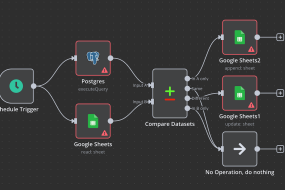
Workflow Pipeline using n8n: If we zoom into what the n8n pipeline might look like, it’s essentially a sequence of nodes each performing a task. A possible sequence: Trigger, for example, an HTTP webhook that the SolidWorks add in calls when the user clicks “Optimise”. Next, a BOM Extraction Node (could be a script node) gets BOM data (if not already provided). Then, Supplier API Nodes might enrich this BOM with pricing and stock info. After that, a Vector Search Node queries the vector DB with key info from the BOM (like each part’s type or any flagged constraint questions). Then an LLM Node (perhaps using n8n’s HTTP request to call Ollama’s API) sends the compiled prompt, which includes context from previous nodes like the BOM and retrieved documents. Once a response comes, further nodes handle Post processing, maybe splitting the response into a structured list or creating an output file. Finally, a SolidWorks Update Node could push results back, or an Email Node might send the supplier ready BOM to procurement. n8n allows branching logic too: for example, if the LLM returns a message that some data was insufficient, a branch could handle that error (perhaps notifying an engineer to provide more input). The pipeline effectively automates data handling so the engineer only sees final insights, not the intermediate plumbing.
Traditional vs AI Optimised BOM Generation: Another useful visual comparison is a timeline or flow of the old way versus the new way. Traditionally (left side), an engineer designs the HPU layout, then manually lists out needed fittings. They might flip through supplier catalogues or past project BOMs to decide part numbers. This involves a lot of tacit knowledge and checking: ensure hose lengths are correct, verify thread compatibility between components, and iterate if something doesn’t fit. This process is linear and heavily manual. Each change in design might mean recalculating hose lengths, updating drawings, and revising the BOM, which then might go to a purchasing team that checks availability, often coming back with messages like “this part is obsolete or out of stock, please find an alternative”. In the AI optimised workflow (right side), many of these steps happen in parallel and automatically. When the engineer is roughly done placing main components, they trigger the AI. The AI instantly cross checks all interfaces and suggests all the right adapters (removing the need for the engineer to manually figure out if a BSP to NPT adapter is needed, for example). It calculates exact hose lengths or recommends standard hose assembly part numbers. It also simultaneously checks availability, so the first BOM the engineer sees is already vetted for stock. The result is fewer iterative loops. In the traditional flow, you might iterate multiple times (design -> review -> fix errors -> BOM -> procurement issues -> back to design). In the AI flow, it’s more one shot: design, then AI optimisation, then a ready BOM, with the AI catching issues early (like flagging a bend radius problem which the engineer would then adjust in CAD before finalising). So the diagram would show on the traditional side many back and forth arrows between design, BOM, and procurement, whereas on the AI side there’s mostly a straight through arrow from design to final BOM, with the AI loop tightening the process internally.
These visuals underscore how the AI driven approach integrates data and processes that were formerly siloed. By connecting CAD, databases, and AI reasoning, the workflow becomes more streamlined and intelligent, reducing the reliance on manual cross checks and tribal knowledge.
Key Technologies and Terms Explained
In implementing this AI driven optimisation system, we’ve touched on various technical concepts and tools. Below is a plain English explanation of these key terms to ensure everything is clear:
- Retrieval Augmented Generation (RAG): RAG is a technique to make AI models more effective by giving them access to external knowledge. A standard LLM might not know specifics of your problem (for example, the exact pressure rating of a Parker hose) because that detail wasn’t in its training data. With RAG, we bridge that gap. The process works by storing reference documents (manuals, spec sheets, prior designs, etc.) in a specialised database and representing them as numerical vectors. When you ask the AI a question, it first retrieves the most relevant pieces of those documents and feeds them into the question context. This way, the AI’s generation is “augmented” by real, up to date information. It’s like doing an open book exam instead of a closed book exam; the AI can quote the book (your data) to give more accurate answers. The benefit is twofold: the AI’s answers are more grounded in facts, reducing the fabrication of wrong information, and you can update the knowledge base at any time, so the system stays current without retraining the model. In our scenario, RAG is what lets the AI say, “Use part number XYZ because it’s rated to 5000 psi, as per the spec”, pulling that detail from a document we provided, instead of guessing.
- Vector Databases: A vector database is a database optimised to store and search high dimensional vectors (which are essentially lists of numbers). Why vectors? In AI, especially NLP, we convert text into vector embeddings, which are numerical representations of the text’s meaning. Similar texts will have vectors that are close together (by cosine similarity, for instance). A vector DB allows us to store thousands of such vectors (from, say, all paragraphs of all our datasheets) and then quickly find which ones are most similar to a new query vector (our question). This is how the RAG retrieval step is implemented. Vector databases make it easy to find semantically relevant information. Unlike a traditional keyword search, they can find relevant text even if it doesn’t share exact words with the query. Popular open source vector DBs include Weaviate, Chroma, and FAISS. In practice, we use a vector DB so that when we ask, “What are the constraints for bending a 1/2 inch tube?”, we don’t need to have an exact matching FAQ. The DB will return any document vector that mathematically matches that context, perhaps a design guide paragraph on tube bending. It’s a cornerstone technology for RAG because it’s what enables that “smart lookup” of information to feed to the LLM.
- Large Language Models (LLMs): LLMs are AI models that are trained to understand and generate human like text. They are called “large” because they have many parameters (often billions) and are trained on vast amounts of text data. The result is a model that has learned grammar, facts, reasoning patterns, etc., to a surprising degree. Models like GPT 4 (from OpenAI) or open alternatives such as Llama 2, GPT J, and DeepSeek R1 fall into this category. They can answer questions, create plans, write code, and more, all by predicting the most likely next words in a sequence, given what’s come so far. For our guide, suffice to say an LLM is the “brain” of the AI assistant that can reason about the design. But by itself, an LLM is general purpose. We tune it for our needs through the prompt and by giving it context (via RAG). One should be aware that LLMs don’t “think” like humans; they generate text based on patterns, so they might sometimes sound confident while being wrong. That’s why coupling with factual retrieval and constraints (our approach) is important. In terms of usage, an LLM can be asked to output structured results (like JSON or tables), which is useful when we want to programmatically read its recommendations. LLMs are essentially our new age expert systems. Instead of hard coding rules for every scenario, we let the LLM’s learned knowledge and language understanding fill in the gaps intelligently.
- Ollama (Local LLM Deployment): Ollama is a tool that simplifies running LLMs on your own machine. Normally, setting up an LLM could involve complex configurations, but Ollama provides a containerised, streamlined way to download models and run them. Think of it as an engine specifically made to run AI models, accessible via simple commands or an API. One strength of Ollama is its support for Modelfiles, which are configuration files describing a model (which base model, which fine tuning adapters to apply, what prompt template to use, etc.). By using Ollama, we gain a few things: easy model management (you can use ollama pull <model> from a library of available ones), and a consistent API interface to generate text or embeddings. For instance, we used Ollama to run DeepSeek R1. Without Ollama, this might require dealing with Python libraries and GPU setup, but with Ollama it’s just a one liner to start a local server serving the model. Running the LLM locally via Ollama aligns with our privacy and control requirements: all data stays in house, and we are not dependent on external service uptime. Plus, as discussed, local deployment means we can customise the model. If we wanted to fine tune it on some company data, we could do that and integrate the resulting weights via an adapter (see below). In summary, Ollama is like the runtime environment for our AI, ensuring the LLM and embedding models operate smoothly on our hardware, and providing hooks (like its Python API or REST endpoints) for n8n to call into.
- Adapters and Modelfiles (Customising LLMs): In the context of Ollama (and modern AI in general), an adapter usually refers to a lightweight add on or fine tuning that you can apply to a base model to specialise it. A common type of adapter is a LoRA (Low Rank Adaptation), which is a small set of weight tweaks that can be merged with the base model’s weights to adjust its behaviour, without retraining the whole model. For example, you might have a base LLM but use a LoRA adapter to give it additional hydraulic engineering knowledge or a different tone. Adapters allow you to fine tune models for specific domains or tasks without the heavy cost of full model training. A Modelfile in Ollama is essentially a recipe that can include a base model, plus any number of these adapters, and other settings like system prompts and templates. It’s analogous to a Dockerfile but for models: you write down what you want included, and Ollama builds a combined model from it. For our purposes, we might not need to create a custom Modelfile if the base model suffices. However, it’s good to know the option exists: if down the line we find the AI isn’t using the right terminology or style, we could introduce a “Hydraulics Adapter” trained on industry manuals, and just reference it in the Modelfile. Also, prompt templates can be specified in a Modelfile or at runtime; these are basically patterns for how to format inputs to the model. For example, a template might ensure that every prompt we send has a specific structure, such as: “[INST] <<SYS>>\nYou are an expert hydraulic designer…<</SYS>>\n<</INST>>”, which frames the model’s role and instructions consistently. The key point is that modelfiles and adapters give us fine grained control over model behaviour beyond plain prompting. We can adjust parameters (like how creative vs deterministic it is), set system messages that always apply, and layer domain specific knowledge. In simpler terms, they are our way to custom tune the AI if needed, akin to training an apprentice with certain guidelines or cheat sheets specific to our domain.
- n8n (Workflow Orchestrator): As introduced earlier, n8n is a workflow automation platform. It’s like a toolbox for connecting different software together in a sequence of steps (a workflow). For those familiar with tools like Zapier or Node RED, it’s in that family, but n8n is open source and very flexible, which makes it popular among technical teams. In our use case, n8n is not doing any heavy AI lifting; rather, it’s ensuring data moves from SolidWorks to the AI and back, and that the various APIs and scripts talk to each other in the correct order. One could certainly hard code all these in a custom Python script, but the advantage of n8n is in maintainability and visibility. The workflow is drawn out like a flowchart of nodes, which is easy to understand at a glance. If we need to change something (say, add a new step to push results to an ERP system), we just add a node and connect it, rather than rewriting code. n8n supports conditional logic (if/else paths), loops, and error catching, all of which are useful for robust automation. For example, if the LLM API fails or times out, n8n can catch that and retry or send an alert. With n8n’s 400+ integrations, if tomorrow we decide to integrate a chat system (for example, to post the optimisation results to a team chat for review), it’s likely just a matter of configuring an existing node. In plain terms, n8n is the automation glue; it doesn’t have an opinion on what our data means, but it knows how to shuffle it around between SolidWorks, databases, and AI in a reliable way. For the engineering team, this means less manual data handling. n8n quietly makes sure everything that needs to happen in the background happens, so using the AI assistant feels as easy as clicking a button and getting results.
With these concepts explained, you hopefully have a clearer picture of the technology stack. We have an AI brain (LLM), given knowledge through RAG (vector DB + retrieval) and guided by rules (constraints DB, adapters if any). We have a means to run that AI on our terms (Ollama, locally, with modelfiles/adapters as needed). And we have a conductor (n8n) ensuring all parts of the orchestra play in sync. Now, let’s look at the tangible benefits this setup brings to our engineers and project managers.
Benefits of AI-Driven Optimisation for Engineers and Project Managers
Implementing an AI driven hydraulic fitting optimisation workflow is an investment of effort, but it yields significant payoffs for both engineers on the ground and the project managers overseeing budgets and timelines. Here are some of the key benefits, and why they matter:
- Faster Quoting and Design Cycles: By automating the BOM generation and fitting selection, what used to take days can potentially be done in hours. Engineers no longer need to manually cross reference catalogues or iterate on designs multiple times to get them right; the AI provides immediate suggestions and corrects many issues early. This speed directly translates to faster quoting for projects. When a client requests a proposal for an HPU design, engineers can produce an optimised BOM and layout in a short time, confident that it’s near optimal. Project managers benefit by being able to respond to opportunities quicker and handle more projects in parallel. Shorter design cycles also mean less overtime and stress on engineering teams when deadlines loom, as many tedious tasks are offloaded to automation.
- Improved BOM Accuracy and Completeness: An AI driven process significantly reduces human errors like forgetting a minor fitting or mis specifying a part. Since the BOM is extracted directly from the CAD model and then enhanced by AI (which won’t “forget” to include the two end fittings on a hose, for instance), the final BOM is comprehensive and up to date with the design. Accuracy is also improved in terms of choosing the right parts. The AI cross checks compatibility and constraints, so the chosen components are the correct ones (threads match, pressure ratings are sufficient, and so on). This means fewer engineering change orders (ECOs) later due to design mistakes. For project managers, a correct BOM means more reliable cost estimates and smoother procurement; they won’t be hit with surprise needs for additional parts mid build or delays because something was wrong. Overall, confidence in BOM accuracy goes up, which is crucial for planning and client trust.
- Cost Optimisation and Simplified Procurement: The AI doesn’t just blindly copy what was done before; it actively searches for ways to reduce costs while meeting requirements. This can involve suggesting standardisation of parts (using the same fitting in multiple places if possible to buy in bulk), or using a single adapter where previously two might have been cascaded. By consulting real time pricing, it might pick a cheaper equivalent component that does the job. For procurement, the BOM that comes out is already optimised for cost and availability, so the purchasing department spends less time sourcing or negotiating. Also, because the system can group by supplier and consider lead times, it simplifies ordering. Long lead items are flagged early, allowing earlier ordering or redesign to avoid them, and the purchasing team gets a neatly organised request rather than a raw list they have to research. In essence, the company can save on material costs and procurement effort, improving the project’s bottom line.
- Enhanced Build Quality and Reliability: When hydraulic fittings and hoses are optimally chosen and routed, the build quality naturally improves. Properly routed hoses with appropriate bend radii last longer and are less prone to failure. Fewer unnecessary connections mean fewer potential leak points. By following all the design constraints, the AI ensures, for example, that no hose is bent too tightly (preventing early hose wear or bursts) and that no tube fitting is placed in a way that’s impossible to wrench. The result is an HPU that is easier to assemble and maintain. Technicians on the shop floor will find the assembly just fits together with less trial and error because the design was vetted. For project managers, higher build quality means fewer warranty issues, higher customer satisfaction, and a better reputation. It also means that testing and commissioning go more smoothly since there are likely no leaks or performance hits from suboptimal plumbing.
- Knowledge Capture and Consistency: A subtle but important benefit is that the AI system encapsulates a lot of institutional knowledge. Instead of each engineer having a slightly different approach to designing the plumbing (with varying results), the AI introduces a level of consistency. It applies the same rules and logic every time, which means all designs start to reflect best practices uniformly. New engineers can ramp up faster; they effectively have a mentor in the AI that guides them on following company standards. The knowledge of seasoned engineers (such as “always include a drain valve at the lowest point” or “use 45 degree adapters on pump outlets to reduce stress”) can be built into the system, so it’s not lost if those engineers retire or are unavailable. For management, this reduces dependency on specific individuals for critical know how and ensures that quality doesn’t vary project to project due to human factors. It’s like raising the baseline competence on repetitive design tasks, freeing human experts to focus on truly novel challenges.
- Better Project Planning and Transparency: Because the AI provides information on part lead times and potential risks upfront, project managers can plan timelines more accurately. If the AI indicates a certain component has an 8 week lead time, the manager can make a call to redesign early or at least inform the client and adjust the schedule accordingly. This proactive risk management is a big shift from reactive firefighting. Additionally, the AI generated outputs (like the rationale for certain choices, or the data on availability) provide transparency. Managers, and even clients, can see why certain decisions were made (for example, “we chose this routing to eliminate two extra elbows, improving system efficiency and reducing cost by £200”). This not only helps in decision making but can be used to communicate value to clients, showing that the design was done with a rigorous, modern approach.
In summary, the move to AI driven fitting optimisation empowers engineers to deliver higher quality work in less time, and gives project managers more predictability and control over project outcomes. It’s a classic case of technology amplifying human capability. The grunt work and detailed optimisation are handled by the AI, while humans oversee, make high level decisions, and handle the creative and complex aspects of system design. The result is a more efficient engineering workflow and superior project execution.
Comparing AI Technology Options for Implementation
Finally, it’s worth comparing the different AI technology approaches we’ve discussed, particularly as they relate to using Ollama and LLMs for our application. There are several ways to customise or enhance an LLM driven solution: using modelfiles, adapters, prompt templates, or a RAG + vector database strategy (or combinations of these). The best approach can depend on the use case. Below is a comparison in table form of these options, outlining what they are, their strengths, and when to use each:
| Approach | Description | Ideal Use Cases | Pros and Cons | Example Scenario |
| Ollama Modelfile (Full Model Customisation) | Using an Ollama Modelfile to define a custom model. This can include a base model plus system prompts, parameters, and possibly integrated adapters (like LoRA fine tunings). Essentially, it’s building a tailored model ‘instance’ for your application. | Great when you want a self contained model that embodies your domain knowledge and style. Use when multiple customisations, such as system messages or certain defaults, are needed consistently. It’s also useful if you plan to share the model setup with others or move it between systems. | Pros: Reproducibility, as all settings are captured, so deploying the model elsewhere yields the same behaviour. Modularity means it’s easy to tweak one aspect (like swapping the base model) and rebuild. It ensures a consistent starting point every time you invoke the model.<br>Cons: Initial effort is needed to set up the Modelfile. If a lot of domain knowledge is required, it might still need fine tuning or adapters, which have to be prepared and referenced. | Example: Creating a “HydraulicsGPT” model via a Modelfile that uses Llama 2 as a base, a custom prompt template for structured BOM outputs, and a system message that it’s an HPU design assistant. Every engineer’s machine can pull this model and get identical results. |
| Adapters (LoRA Fine Tunes) | Attaching adapter modules (like Q LoRA or other fine tuned weights) to a base model. This is a lightweight way to inject domain specific knowledge or behaviour without altering the main model weights. Ollama supports applying adapters via Modelfile instructions. | Use when you have specialised data to teach the model or need it to adopt a specific tone or skill. Ideal for domain specific jargon or knowledge, especially if our vector DB approach wasn’t enough by itself. Also useful to reduce hallucinations in a certain domain by fine tuning on Q&A pairs. | Pros: Relatively low compute cost to train (you can fine tune on a small set of data). Can dramatically improve performance on niche tasks. Doesn’t require hosting a separate huge model; just load the adapter onto the base model as needed.<br>Cons: Maintains separate adapter files and versions, which adds complexity in managing them. Fine tuning needs data; if you lack a good dataset, an adapter might not be effective. Overfitted adapters could make the model too rigid or cause it to forget some general capabilities. | Example: Training a LoRA adapter on a set of 1,000 Q&A pairs from hydraulic design manuals, so the LLM more accurately handles technical questions. We then use ADAPTER hydraulic_lora.bin in our Modelfile. When asked something like, “explain the difference between JIC and ORFS fittings”, the model answers with authority using that training. |
| Prompt Templates (Prompt Engineering) | Designing and using prompt templates to guide the model’s outputs. This involves structuring the input text or including predefined instructions so that the model knows the expected format and style. There are no changes to the model’s weights; it’s purely how you ask it. | Use for formatting outputs, for example, always produce a table or JSON. Use to imbue context or persona without needing an adapter, for instance, a system prompt like “You are a seasoned hydraulic engineer…”. Ideal for when the model mostly works out of the box, but you need to nudge it to follow certain rules or formats. | Pros: No special tools needed, just craft the text. Very flexible and quick to iterate; just edit the text if outputs are not as desired. Combines well with other methods (still needed even if using RAG or adapters, to frame the task).<br>Cons: Can be brittle, as models might ignore or deviate from instructions, especially under pressure to solve something. Prompt engineering can become trial and error, and hidden tokens count towards input length. It doesn’t add new knowledge, only helps present or obtain what the model already knows (or is given via RAG). | Example: We create a prompt template in our Modelfile that ensures the output is, first, a summary of changes, then a JSON list of BOM items. The template might also inject a caution like, “Do not propose non standard parts.” This way, every time the model is invoked via our workflow, we get a consistent, structured answer that our code can parse. |
| RAG + Vector Database (External Knowledge) | Integrating a retrieval system with the LLM, so that it can use an external knowledge base at query time. We feed the model with relevant text snippets from the vector DB (as discussed in RAG). This approach relies on storing information externally rather than in the model. | Use when you have a lot of reference data (like specifications or documents) that is too large or dynamic to fine tune into the model. Ideal for scenarios requiring up to date information or user/project specific data (such as each project’s past decisions or client preferences). Great for maintaining a smaller base model but giving it large, effective knowledge via the DB. | Pros: No need to retrain the model to update knowledge; just add or update documents in the database, and the model can use them. Scales well: you can have a huge knowledge base, and the retrieval will still pull only what’s needed. Reduces hallucination by grounding answers in retrieved text. Allows using one general model for multiple contexts (just swap out the data).<br>Cons: More moving parts, as it requires maintaining the vector DB and an embedding model. If the retrieval fails or misses something, the model might not know how to answer correctly. Also, the model’s answer length limits how much context you can give; complex questions might need many snippets and could hit those limits. Requires careful design of the prompt to cite the information correctly. | Example: Instead of fine tuning a model on a 500 page catalogue (which would be impractical), we load the catalogue into a vector DB. When asked, “What fittings do I need to connect component X to Y?”, the system pulls the pages about X and Y’s ports from the catalogue and gives them to the LLM. The LLM then answers, citing those specifications (for example, “Component X has an SAE 12 port, Component Y has an SAE 10; use a reducer fitting part number 12345 to adapt sizes”). If tomorrow the catalogue updates or a new part is added, we just update the DB, with no retraining needed. |
When to Use Which: In practice, these methods are not mutually exclusive; they often complement each other. For our hydraulic fitting optimiser, we leaned heavily on RAG plus a vector DB because of the breadth of reference information and the need for up to date data regarding parts and constraints. This allowed us to keep the base model generic but knowledgeable. We used prompt templates to format output and set the tone (ensuring the model’s suggestions were given as clear steps and BOM lists). We did not immediately need custom adapters or a custom modelfile beyond basic configuration, since a good open model plus RAG covered our needs. However, if in future we find certain repetitive reasoning errors or want an even more specialised touch, we might train an adapter (say on our company’s past design Q&As) to further tune the model’s responses.
Summing it all up
- Start with prompt engineering and RAG, as these give you a lot of mileage by guiding the model and giving it knowledge, without heavy development. They are usually the first tools to reach for, as we did for getting spec compliance and format from the AI.
- Use modelfiles and adapters when you find the base model isn’t quite hitting the mark or when you want to package the solution for wider distribution. Adapters are like giving the model a short course in a subject, while modelfile ensures the model runs with all your desired settings out of the box.
- Always weigh effort versus benefit: RAG requires infrastructure but low maintenance of content; fine tuning (adapters) requires data and training but then is easier at runtime. Prompting is easy but can only bend the model so far if it lacks knowledge.
By understanding these options, you can make informed decisions on how to maintain and evolve your AI driven system. As your company’s needs grow, you might incorporate more of these techniques – for example, creating a company specific model through a modelfile that multiple teams use, or training adapters for different domains (perhaps one for hydraulics, one for electrical schematics, etc., all used with the same base LLM). The table above should serve as a quick reference when deciding “How should I improve my AI’s performance or scope?” in the context of the tools at your disposal.
By implementing the above guide, engineering teams with intermediate knowledge of hydraulics, CAD, and AI should be well equipped to develop and benefit from an AI driven workflow for hydraulic fitting optimisation. The synergy of human expertise and AI assistance promises not only to save time and cut costs but also to elevate the quality and reliability of HPU builds. With careful development, integration, and continuous learning, this AI driven approach can become a trusted standard in your design process, much like simulation tools or CAD itself, ultimately enabling faster, smarter, and more competitive project execution.