From Bits to Waves: Exploring Digital and Analog I/O
Digital and analog inputs and outputs play a crucial role in process control within engineering, serving as the primary means through which a Programmable Logic Controller (PLC) interacts with the physical environment. The Siemens S1200 PLC, a compact and versatile controller, offers a wide range of inputs and outputs to accommodate various industrial applications. This article delves into the significance and applications of these inputs and outputs in the context of process control.
Digital Inputs and Outputs
Digital inputs and outputs are fundamental to the operation of the Siemens S1200 PLC in process control systems. Digital inputs are used to receive binary signals (on/off, true/false) from various devices such as sensors, switches, and push buttons. These inputs inform the PLC about the current state of different parts of the process, allowing for condition-based decision-making.
Digital outputs, on the other hand, enable the PLC to control actuators, relays, and other devices by sending binary signals. This allows the PLC to effect changes in the process, such as starting or stopping motors, opening or closing valves, and triggering alarms.
The Siemens S1200 PLC is equipped with high-speed digital inputs and outputs that support fast response times, making it suitable for applications requiring precise timing, such as pulse counting or high-speed part sorting.
Analog Inputs and Outputs
Analog inputs and outputs add another layer of sophistication to process control systems. Unlike digital signals, analog signals can represent a range of values, making them ideal for monitoring and controlling variables that change continuously, such as temperature, pressure, flow rate, and level.
The Siemens S1200 PLC’s analog inputs can process signals from various transducers and sensors, converting physical quantities into electrical signals that the PLC can interpret. This enables the PLC to continuously monitor the process conditions and make adjustments in real-time to maintain optimal performance.
Analog outputs from the Siemens S1200 PLC allow for precise control over actuators, such as control valves, by varying the signal sent to the device. This fine-grained control is essential in processes where maintaining a specific setpoint or following a precise control curve is crucial.
Integration in Process Control
The integration of digital and analog inputs and outputs in the Siemens S1200 PLC facilitates comprehensive process control. By combining the binary control and monitoring capabilities of digital I/O with the continuous measurement and control offered by analog I/O, the S1200 PLC can manage a wide array of industrial processes.
Moreover, the Siemens S1200 PLC supports seamless integration with other Siemens automation components, such as Human Machine Interfaces (HMIs) and SCADA systems, enabling centralised control and monitoring of the entire process.
In process control engineering, the Siemens S1200 PLC stands out for its robust support for digital and analog inputs and outputs. This versatility allows engineers to design and implement sophisticated control systems capable of managing the complexities of modern industrial processes. By leveraging the unique capabilities of both digital and analog I/O, the S1200 PLC ensures precise control, efficient operation, and high reliability in various industrial applications.
Engineering principles and theories
The engineering principles and theories that underpin the use of digital and analog inputs and outputs in a Siemens S1200 PLC, especially in the context of process control, are grounded in several core areas of electrical and control engineering. These include signal processing, feedback control theory, automation, and digital electronics, which together facilitate the effective design and operation of process control systems.
Signal Processing
Signal processing involves the analysis, manipulation, and interpretation of signals to extract useful information or to produce desired signals. In the context of PLCs, analog inputs undergo signal processing to convert physical parameters (like temperature or pressure) into electrical signals that can be digitally sampled and analysed. Analog-to-digital converters (ADCs) in the PLC perform this conversion, applying concepts such as sampling theorem and quantisation. These principles ensure that the continuous analog signals are accurately represented in the digital domain for processing.
Feedback Control Theory
Feedback control is a fundamental theory in process control that involves comparing a system’s output to a desired setpoint and using the difference (error) to adjust inputs to the system to achieve the desired output. PLCs, like the Siemens S1200, use this principle in both digital and analog control loops. For analog control, Proportional-Integral-Derivative (PID) algorithms are commonly implemented within PLCs to continuously adjust control outputs, such as valve positions or motor speeds, based on feedback from process sensors.
Automation and Programmable Logic
Automation principles are at the core of PLC operation, where a set of predefined instructions or logic is executed to control industrial processes automatically. The Siemens S1200 PLC uses a programming language (such as Ladder Logic, Function Block Diagram, or Structured Text) that allows engineers to implement complex logic operations, sequential control, and timing functions. This is based on the theory of finite state machines and digital logic, where the system’s state is controlled based on input conditions and logical operations.
Digital Electronics and Microcontroller Theory
The operation of digital inputs and outputs in a PLC is grounded in digital electronics, particularly the theory of microcontrollers and digital circuits. Digital inputs are interfaced with the PLC through optical isolators and similar components to protect against voltage spikes and electrical noise. Digital outputs often use transistors, relays, or other switching components to control actuators. The principles of Boolean algebra are applied to process digital signals within the PLC, enabling decision-making and control actions based on the combination of input signals.
Integration and Communication
Modern process control systems require the integration of various components and communication between them. The Siemens S1200 PLC employs industrial communication protocols (like PROFINET) and supports networked configurations to facilitate this integration. This is underpinned by theories in computer networking and communication systems, ensuring reliable and timely data exchange between the PLC and other devices, such as sensors, actuators, and human-machine interfaces.
By applying these engineering principles and theories, the Siemens S1200 PLC is equipped to handle the complexities of process control, enabling efficient and reliable operation of industrial systems. These principles ensure that the PLC can accurately process input signals, make decisions based on programmed logic, and execute control actions to maintain desired process conditions.

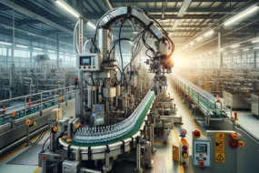
Real-world example: A Bottling Plant
A real-world example that illustrates the use of both digital and analog inputs and outputs within the context of a Siemens S1200 PLC is a modern bottling plant. This example encompasses various stages of the bottling process, from filling and capping to labelling and packaging, showcasing the diverse applications of digital and analog I/O in managing and optimising each phase.
Stage 1: Filling
In the filling stage, bottles are filled with a liquid product to a precise volume. Analog inputs are critical here, as they monitor the level of liquid in each bottle using level sensors. These sensors provide continuous feedback to the PLC, which then controls the filling valves via analog outputs. The analog outputs regulate the valve opening, ensuring each bottle is filled to the exact required volume, demonstrating the application of analog control for precision tasks.
Stage 2: Capping
Once filled, the bottles move to the capping station, where caps are automatically placed and tightened. Digital inputs play a key role here, detecting the presence of a bottle and a cap using proximity sensors. This triggers the capping mechanism, controlled by digital outputs, which activate pneumatic actuators to place and tighten the caps. This stage highlights the use of digital I/O for on/off control tasks that require binary decisions.
Stage 3: Labeling
In the labelling stage, labels are applied to the bottles. This process involves both digital and analog controls. Digital inputs detect the bottle’s presence and ensure the label applicator is in the correct position. Analog inputs might be used to measure the tension in the label roll, providing feedback to the PLC, which then adjusts the motor speed via analog outputs to maintain consistent tension, ensuring the smooth application of labels. This stage illustrates the integration of digital and analog I/O for tasks requiring both binary and continuous control.
Stage 4: Quality Control
Quality control is vital to ensure that only products meeting the required standards proceed to packaging. Here, digital inputs are used extensively, with sensors checking for the presence of a cap, label, and correct fill level. Additionally, vision systems, which can be considered as providing analog inputs, capture detailed images of each bottle, analysing them for defects such as incorrect labelling or fill level. The PLC processes this information, making real-time decisions to reject defective products.
Stage 5: Packaging
In the final stage, bottles are grouped and packaged for shipment. Digital outputs control the conveyors and packaging machinery, directing the movement of bottles into packaging units. Analog outputs may adjust the speed of conveyor belts to match the packaging rate, ensuring a smooth flow. This stage demonstrates the use of digital outputs for direct control of machinery and analog outputs for adjusting operational parameters.
Integration and Monitoring
Throughout the process, the Siemens S1200 PLC integrates the various stages, ensuring they operate cohesively. The PLC’s digital and analog I/O capabilities allow for precise control and monitoring, adapting to real-time feedback and ensuring high efficiency and product quality. Moreover, the PLC can communicate with other systems, such as inventory management and SCADA, for comprehensive control and oversight of the entire bottling operation.
This bottling plant example underscores the versatility and utility of digital and analog inputs and outputs in a Siemens S1200 PLC, showcasing their essential roles in a wide range of industrial automation tasks.
Reading and Troubleshooting Digital and Analog signals
Reading analog and digital signals involves understanding their fundamental differences and how they represent information:
Analog Signals:
- Continuous Nature: Analog signals are continuous, meaning they can represent a range of values within certain limits. Think of analog signals like a dimmer switch for a light, where you can adjust the brightness to any level between off and fully on.
- Reading Techniques:
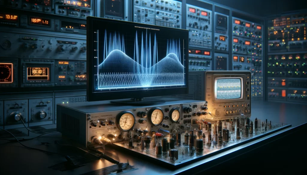
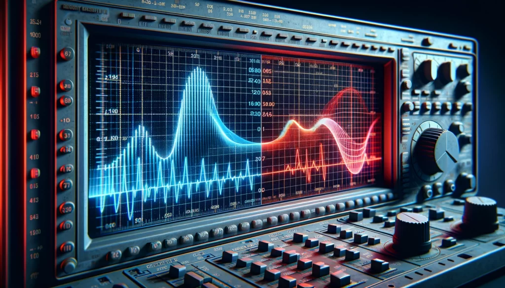
- Visual Inspection: Using tools like oscilloscopes, you can view the waveform of an analog signal. The vertical axis typically represents voltage (or current), and the horizontal axis represents time.
- Measurement Instruments: Multimeters, voltmeters, and ammeters can measure specific aspects of an analog signal, like its average, RMS (Root Mean Square) voltage, or peak-to-peak voltage.
- Interpretation: The shape of the waveform, such as sinusoidal, triangular, or sawtooth, gives information about the signal’s nature. The amplitude represents the signal strength, while the frequency indicates how fast the signal is changing.
Digital Signals:
- Discrete Nature: Digital signals represent information in binary format, using two distinct levels or states, often referred to as ‘1’ and ‘0’. This is akin to a light switch, which can only be off or on.
- Reading Techniques:
- Digital Displays: Devices like digital oscilloscopes can show digital signals’ high and low states, often representing them as square waves.
- Logic Analysers: These are used for more complex digital signals, like those in digital communication or computing systems, to read and decode sequences of bits.
- Interpretation: The key aspects to observe are the timing (how fast the signal transitions between ‘0’ and ‘1’) and the logic levels (what voltages are considered ‘0’ and ‘1’). Timing diagrams can help understand the sequence and duration of states in a digital signal.
Comparing the Two:
- Analog: More nuanced and capable of representing a wide range of values, but can be more susceptible to noise and signal degradation.
- Digital: Offers precise, clear states that are easier to interpret by digital systems and are generally more resistant to noise, but lack the smooth gradation of analog signals.
Understanding and interpreting these signals is fundamental in fields like electronics, telecommunications, and process control, where sensors might output analog signals representing temperature or pressure, while digital signals might control motors or indicate the status of a system.
Troubleshooting digital and analog signals involves different approaches due to their inherent characteristics. Here are some strategies for each:
Troubleshooting Analog Signals:
- Verify the Source: Ensure the signal source, whether it’s a sensor or a transmitter, is powered and functioning correctly.
- Check the Continuity: Use a multimeter to check the continuity of the signal path. Broken wires or loose connections can disrupt the signal flow.
- Inspect the Signal Quality: Use an oscilloscope to observe the signal waveform. Look for distortions, noise, or deviations from the expected waveform, which can indicate interference or signal degradation.
- Measure Signal Levels: Ensure the signal levels are within the expected range. Signals that are too weak or too strong can indicate issues with the source or the receiving equipment.
- Filter Noise: Analog signals can pick up noise from various sources. Use filtering techniques or shielded cables to minimise interference.
- Calibrate Equipment: Regular calibration of measurement and signal-generating equipment is essential to maintain accuracy.
Troubleshooting Digital Signals:
- Check Logic Levels: Use a digital multimeter or a logic probe to check that the high and low levels of the digital signal match the expected logic levels of the system.
- Examine Signal Integrity: Digital signals can suffer from issues like jitter, reflections, and timing errors. An oscilloscope or a logic analyser can help identify these problems.
- Verify Timing: Ensure that the timing of the digital signal aligns with the system’s requirements. Timing issues can cause data corruption or communication failures.
- Inspect Power Supply: Fluctuations or instability in the power supply can affect digital circuits. Verify that the supply voltages are stable and within the specified limits.
- Look for Short Circuits or Opens: Check the circuit for any short circuits or open connections that might be causing the digital signal to be lost or altered.
- Review Circuit Design: Incorrect circuit design or component choice can lead to digital signal issues. Ensure that the circuit meets the required specifications for signal speed, impedance, and termination.
General Tips for Both Analog and Digital Signals:
- Consult Documentation: Manufacturer datasheets and system schematics can provide valuable information for troubleshooting.
- Isolate the Problem: Systematically isolate different parts of the system to narrow down the source of the problem.
- Consider Environmental Factors: Temperature, humidity, and electromagnetic interference can affect signal quality. Ensure the operating environment is within specified limits.
- Use Known Good Components: Swap out suspect components with known good ones to identify faulty parts.
Troubleshooting often involves a process of elimination, starting with the most common issues and gradually working through potential problems until the root cause is identified.