Process control in engineering is a multidisciplinary field that plays a crucial role in the automation and optimisation of industrial processes. It involves the use of algorithms, sensors, and actuators to regulate the operation of machines and processes to achieve desired outcomes. The goal of process control is to maintain the output of a specific process within a desired range, ensuring the efficient and safe operation of the system.
Fundamentals of Process Control
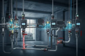
At the heart of process control is the concept of a feedback loop, which is used to continuously adjust the process to maintain the desired output. Sensors measure the process variable (e.g., temperature, pressure, flow rate) and send this information to a controller. The controller then compares the actual value to the desired setpoint and adjusts the process through actuators to maintain the setpoint.
Types of Process Control
Process control systems can be classified into two main types: open-loop and closed-loop control systems.
- Open-loop Control: In an open-loop control system, the control action is independent of the output. This type of control is simpler but less accurate since it doesn’t correct for disturbances or changes in the process.
- Closed-loop Control: Closed-loop control systems, also known as feedback control systems, adjust the control action based on the output. This system is more complex but provides higher accuracy and stability by compensating for disturbances.
Advanced Process Control (APC)
Advanced process control involves the use of sophisticated algorithms and techniques to improve the performance of basic control systems. APC encompasses a variety of approaches such as model predictive control (MPC), adaptive control, and fuzzy logic control. These methods enable the handling of complex, multivariable systems and the optimisation of process performance.
Applications of Process Control
Process control finds applications in numerous industries, including chemical manufacturing, oil refining, power generation, food processing, and pharmaceuticals. In each of these industries, process control is critical for maintaining product quality, maximising efficiency, reducing waste, and ensuring safety.
Challenges and Future Directions
The field of process control is continuously evolving with advances in technology. The integration of Internet of Things (IoT) devices, big data analytics, and artificial intelligence (AI) offers new opportunities for more sophisticated and autonomous control systems. However, these advancements also bring challenges in terms of cybersecurity, data management, and the need for skilled professionals.
Engineering principles and theories
The engineering principles and theories behind process control are foundational to understanding how systems are regulated and optimised in industrial settings. These principles enable engineers to design systems that can maintain desired performance levels despite changes in external conditions or system variables. Below are some key concepts and theories integral to process control in engineering:
Control Theory
Control theory is the backbone of process control engineering, providing a mathematical foundation for analysing and designing control systems. It involves the study of how systems behave and how their behaviour can be modified through feedback. Key concepts in control theory include:
- Stability: This refers to a system’s ability to return to its equilibrium state after a disturbance. Stability analysis helps engineers design systems that remain predictable and safe under varying conditions.
- Feedback Loops: Feedback loops are central to control systems, allowing the system to adjust its output based on the difference between the actual output and the desired setpoint. Positive feedback amplifies system output, while negative feedback reduces it, typically leading to system stability.
- Transfer Functions: These mathematical representations describe the relationship between the input and output of a system, taking into account the system’s dynamics. Transfer functions are used to analyse system behaviour and design appropriate controllers.
System Dynamics
Understanding the dynamic behaviour of systems is crucial in process control. System dynamics involves the study of how system variables evolve over time under the influence of external inputs. It includes:
- Time Constants and Delays: These parameters describe how quickly a system responds to changes. Time constants represent the speed of the system’s response, while delays represent the time it takes for an input change to start affecting the system’s output.
- Oscillations and Damping: In many control systems, particularly those involving mechanical components, oscillations can occur. Damping is the mechanism by which oscillations decrease over time due to energy loss in the system.
PID Control
Proportional-Integral-Derivative (PID) control is a widely used control mechanism in engineering. It combines three types of control actions:
- Proportional Control (P): This action produces an output that is proportional to the current error value. It provides immediate response but can lead to steady-state error.
- Integral Control (I): This action responds to the accumulation of past errors, helping to eliminate the steady-state error but potentially leading to overshoot and instability.
- Derivative Control (D): This action responds to the rate of change of the error, providing a damping effect that improves stability and reduces overshoot.
Cybernetics
Cybernetics explores the regulatory and communication aspects of living organisms, machines, and organisations. Its principles, such as feedback and homeostasis, have been applied to process control to develop systems that can self-regulate and adapt to changing environments.
Model-Based Control
Model-based control strategies, such as Model Predictive Control (MPC), use mathematical models of the process to predict future behaviour and optimise control actions. These methods are particularly useful for complex, multivariable systems with constraints.

A practical illustration – Bottling Plant
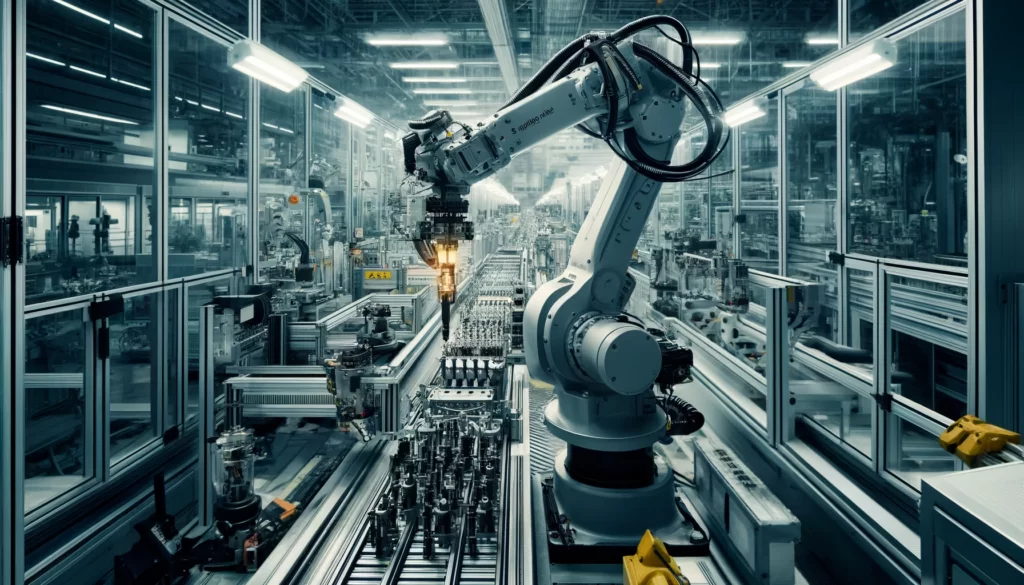
A practical illustration of process control in the engineering domain can be seen in a bottling plant automation system using the Siemens S1200 PLC (Programmable Logic Controller) and the TIA Portal software. This real-world example showcases the application of process control principles to achieve precision, efficiency, and reliability in a high-speed production environment.
Background
The Siemens S1200 PLC is part of the SIMATIC S7-1200 family, designed for compact automation projects. It is widely utilised in various industrial applications due to its high performance, integrated interfaces, and versatile communication options. The TIA (Totally Integrated Automation) Portal is an engineering framework developed by Siemens that enables seamless project configuration, programming, and management of automation devices such as PLCs, HMIs (Human Machine Interfaces), and drives.
Bottling Plant Automation Overview
In a typical bottling plant, the process involves multiple stages, including bottle washing, filling, capping, labelling, and packaging. Each of these stages must be meticulously controlled to ensure product quality, maximise throughput, and minimise waste.
System Design and Implementation
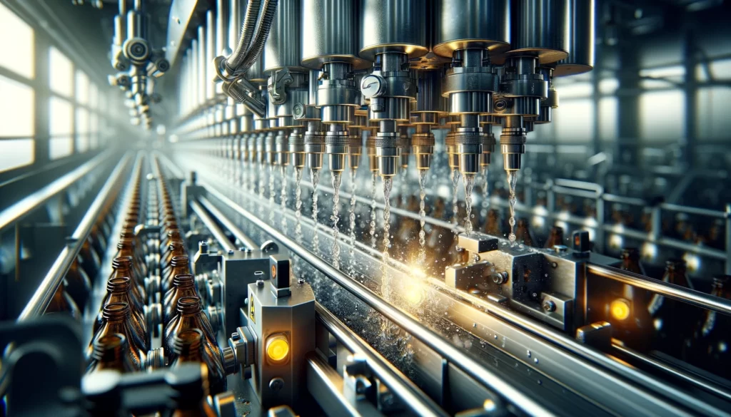
- Bottle Washing: The first stage in the bottling process involves cleaning the bottles. Sensors are installed to detect the presence of bottles and trigger the washing mechanism. The Siemens S1200 PLC is programmed to open the water valves for a specific duration, ensuring thorough cleaning. The PLC monitors the flow rate and temperature of the water, adjusting the valves to maintain optimal washing conditions.
- Filling: After washing, bottles are moved to the filling station. The PLC controls servo motors that position the bottles under the filling nozzles. Flow sensors provide feedback to the PLC, which opens the valves to dispense the liquid. The filling process must be precise to ensure consistent product volume in each bottle. The PLC uses PID control to adjust the valve opening based on the flow rate and the desired setpoint.
- Capping: Once filled, bottles are capped. A capping machine equipped with torque sensors ensures that caps are securely fastened. The PLC adjusts the torque applied by the capping heads to avoid damaging the caps or bottles, ensuring a tight seal.
- Labeling and Packaging: The final stages involve applying labels and packaging the bottles. The PLC coordinates the operation of label applicators and packaging machinery, synchronising their speeds with the production line to avoid bottlenecks.
- TIA Portal Integration: The entire process is configured and monitored using the TIA Portal. This software provides a unified environment for programming the PLC, designing the HMI interfaces, and integrating other components like drives and network devices. The TIA Portal offers diagnostic tools, data logging, and visualisation capabilities, allowing for real-time monitoring and adjustments to the process.
Benefits and Outcomes
- Efficiency: The automated system maximises throughput by minimising manual interventions and downtime.
- Consistency: Precise control over each stage of the bottling process ensures consistent product quality.
- Flexibility: The system can be easily reconfigured for different bottle sizes and products, thanks to the modular design and programmable nature of the PLC.
- Scalability: Additional modules can be integrated into the PLC to expand its capabilities, allowing the system to grow with the plant’s needs.
Summary
This example demonstrates how process control principles when applied using advanced tools like the Siemens S1200 PLC and TIA Portal, can transform industrial operations. The integration of sensors, actuators, and control logic enables the automation of complex processes, delivering efficiency, precision, and scalability in a high-demand production environment like a bottling plant.

How to choose your programming paradigms and methodologies
In the context of programming for a bottling plant using Siemens TIA Portal, it’s essential to choose programming paradigms and methodologies that enhance the readability, maintainability, and scalability of the automation software. The TIA Portal supports various programming languages and paradigms under the IEC 61131-3 standard, which can be effectively employed to address the different needs of the bottling plant processes. Let’s break down the processes and discuss suitable programming paradigms for each:
1. Bottle Washing Process
Ladder Logic (LAD): Ideal for simple control circuits, Ladder Logic is intuitive for engineers familiar with electrical diagrams. For the bottle-washing process, where actions are mostly sequential and involve basic control of valves and sensors, Ladder Logic can provide clear and straightforward program structures.
- Sensors Activation: Use LAD to create conditions based on input from presence sensors to initiate the washing cycle.
- Valve Control: Implement straightforward ON/OFF controls for water valves with time delays to ensure thorough washing.
2. Filling Process
Function Block Diagram (FBD): For controlling the filling operation, which requires more complex logic involving analog signals from flow meters and precise control of valves, FBD is suitable. It allows for a visual representation of the control loops and data flow, making PID control implementations more manageable.
- PID Control Blocks: Utilise built-in PID control blocks for managing the flow rate and volume during filling, ensuring consistent product quantity.
- Analog Input Processing: Employ function blocks to handle analog inputs from flow sensors, converting them to meaningful control signals for the valves.
3. Capping Process
Structured Text (ST): Given the need for precise control over the torque and the sequence in which bottles are capped, Structured Text can offer the flexibility and sophistication required for implementing the algorithms that govern the capping heads’ movement and torque control.
- Torque Control Algorithms: Implement algorithms in ST to adjust the torque based on feedback from torque sensors, ensuring optimal cap tightness without damaging the bottles.
- Sequence Control: Use ST for programming complex sequences and conditional operations, providing flexibility in controlling the capping process based on real-time sensor data.
4. Labeling and Packaging Process
Sequential Function Chart (SFC): The labelling and packaging stages involve a series of steps that need to be performed in a specific order, often with conditional branching. SFC is particularly well-suited for modelling such processes, as it visually represents the sequence of operations and transitions between them.
- Process Steps Visualisation: Utilise SFCs to outline the sequence of actions in the labelling and packaging process, making the workflow easy to understand and modify.
- Conditional Transitions: Implement transitions in SFCs based on conditions such as the completion of labelling or the arrival of packaging materials, ensuring smooth flow through the process stages.
5. Overall System Integration and Monitoring
Continuous Function Chart (CFC): For overseeing the integration of all processes and for system-wide monitoring, CFC provides a canvas to drag and drop and interconnect function blocks and other program elements freely, offering a high-level view of the entire bottling plant control logic.
- System Integration: Use CFC to connect various process control blocks, enabling seamless data exchange and coordinated control across the bottling plant.
- Monitoring and Diagnostics: Implement comprehensive monitoring and diagnostic blocks within the CFC framework to facilitate real-time tracking of system performance and quick troubleshooting.
Selecting the appropriate programming paradigms for different aspects of the bottling plant automation in TIA Portal is crucial for creating an efficient, reliable, and maintainable control system. By leveraging the strengths of each programming language and paradigm—Ladder Logic for simple control tasks, Function Block Diagram for analog process control, Structured Text for complex algorithms, Sequential Function Chart for process sequencing, and Continuous Function Chart for system integration—engineers can design a robust automation solution tailored to the specific needs of a bottling plant.
Creating a TIA Portal program for a bottling plant
Creating a TIA Portal program for a bottling plant involves multiple steps and components that must be orchestrated to work together seamlessly. We’ll start with an overview of the top-level structure and then break down the individual processes involved in a typical bottling plant operation.
Top-Level Program Structure
- Main Program (OB1)
The main organisation block that coordinates the execution of various control tasks and routines. - Hardware Configuration
Setup of PLC modules, input/output configurations, network settings, and any connected devices like HMI panels. - Global Data Blocks (DBs)
These store global variables and parameters that are accessible throughout the program, such as setpoints, system status flags, and counters. - Function Blocks (FCs/FBs)
Modular pieces of code that perform specific tasks, like PID control for liquid filling, conveyor control, and safety checks. These can be reused across different parts of the program. - Human-Machine Interface (HMI)
Screens and controls for operator interaction, displaying system status, manual controls, and alarms.
Process Breakdown
1. Bottle Washing
- Function Block (FB_BottleWash)
- Inputs: Start, Stop, BottlePresentSensor
- Outputs: ValveControl, PumpControl
- Logic: Sequence of operations to wash bottles when a bottle is detected by the sensor. Includes safety interlocks to stop operation if necessary.
2. Filling
- Function Block (FB_BottleFill)
- Inputs: Start, Stop, FillLevelSensor
- Outputs: ValveControl
- Logic: Controls the filling valves to dispense the precise amount of liquid into each bottle, using PID control to adjust the flow rate.
3. Capping
- Function Block (FB_BottleCap)
- Inputs: Start, Stop, CapFeedSensor
- Outputs: CapperControl
- Logic: Manages the capping mechanism, ensuring caps are securely placed on each filled bottle.
4. Labeling
- Function Block (FB_BottleLabel)
- Inputs: Start, Stop, LabelSensor
- Outputs: LabelApplicatorControl
- Logic: Controls the label applicator to affix labels accurately on the bottles.
5. Packaging
- Function Block (FB_BottlePack)
- Inputs: Start, Stop, BoxReadySensor
- Outputs: PackagingControl
- Logic: Coordinates the final packaging of the bottles into boxes for distribution.
6. Conveyor System Control
- Function Block (FB_ConveyorControl)
- Inputs: Start, Stop, EmergencyStop
- Outputs: ConveyorMotorControl
- Logic: Manages the conveyor belts that transport bottles through each stage, including interlocks for safety and efficiency.
7. Safety and Alarms
- Function Block (FB_SafetyChecks)
- Inputs: SafetySensors, EmergencyStop
- Outputs: Alarm, SystemHalt
- Logic: Constantly checks for safety conditions and triggers alarms or halts the system in case of a hazard.
Implementation Notes
- Each process step is encapsulated within its own function block, allowing for modular programming and easier troubleshooting.
- Global data blocks hold system-wide parameters, like operation modes or system status flags, to maintain consistency and ease of access across the program.
- The main program (OB1) orchestrates the execution of these blocks, ensuring they are activated in the correct sequence and under the right conditions.
- HMI integration allows operators to monitor the system, manually intervene if necessary, and acknowledge alarms or warnings.
This outline provides a structured approach to designing a TIA Portal program for a bottling plant, ensuring a clear separation of concerns and modular design for easy maintenance and scalability.

Implementing the FB_BottleWash function block
To implement the FB_BottleWash function block in a TIA Portal project, we’ll outline the code structure and logic sequence to perform the bottle-washing operation. This example assumes familiarity with TIA Portal’s programming environment and basic programming constructs such as data blocks, function blocks, and network configuration.
FB_BottleWash Function Block Structure
Inputs:
Start: BOOL – Signal to initiate the washing cycle.
Stop: BOOL – Signal to halt the washing cycle.
BottlePresentSensor: BOOL – Sensor input indicating the presence of a bottle.
Outputs:
ValveControl: BOOL – Controls the water valve for washing.
PumpControl: BOOL – Controls the pump for water circulation.
Static Variables:
InOperation: BOOL – Indicates that the washing cycle is active.
Timer: TON – Timer for controlling the washing duration.
Step-by-Step Logic:
- Initialisation: Ensure that all outputs are set to a safe state upon starting. This usually means turning off valves and pumps.
ValveControl := FALSE;
PumpControl := FALSE;
Start Sequence: When the Start signal is received and a bottle is detected by the sensor, initiate the washing process.
IF Start AND BottlePresentSensor THEN
    InOperation := TRUE;
    Timer.IN := TRUE;  // Start the timer
ELSE
    InOperation := FALSE;
    Timer.IN := FALSE;  // Stop the timer
END_IF;
Safety Interlock: Implement a safety check to immediately stop the operation if the Stop signal is active, regardless of the current state.
IF Stop THEN
    InOperation := FALSE;
    Timer.IN := FALSE;
END_IF;
Washing Operation: While in operation, open the valve and run the pump for a specified duration to wash the bottle.
IF InOperation THEN
    ValveControl := TRUE;  // Open the water valve
    PumpControl := TRUE;   // Start the pump
    Timer.PT := T#10s;     // Set the washing time (e.g., 10 seconds)
END_IF;
Completion: Once the timer elapses, conclude the washing cycle by resetting the controls and the InOperation flag.
IF Timer.Q THEN
    ValveControl := FALSE; // Close the water valve
    PumpControl := FALSE;  // Stop the pump
    InOperation := FALSE;
    Timer.IN := FALSE;     // Reset the timer
END_IF;
Update Timer: Make sure to continuously update the timer instance with the current system time.
Timer();Implementation Notes:
- Adjust the timer duration (
Timer.PT) based on the required washing time for your specific application.
- Ensure that all hardware interfaces (e.g., I/O addresses for
ValveControl,PumpControl, andBottlePresentSensor) are correctly mapped in your TIA Portal project.
- This basic example does not include advanced error handling or diagnostics, which are crucial for a robust industrial application. Consider implementing additional features such as fault detection, operation logging, and system status indicators.
This function block provides a foundational structure for the bottle-washing process, which can be further customised and extended based on the specific requirements of your bottling plant operation.

Summary
Process control in engineering is crucial for the automation and enhancement of industrial operations. By employing diverse control methods and cutting-edge technologies, engineers are able to markedly boost the efficiency of processes, the quality of products, and the safety of systems. With ongoing technological progress, process control is set to become even more pivotal in driving the evolution of manufacturing and production sectors.
The underlying principles and theories of process control in engineering span an extensive array of mathematical, physical, and computational disciplines. Ranging from basic control theory tenets to sophisticated model-based approaches, these principles inform the development and refinement of systems to ensure they operate efficiently, reliably, and safely across a variety of industrial settings.