A Project Engineer’s Guide to Fixtures for the Automotive Industry
Design intent is about why we make a product a certain way, focusing on goals like how it looks, feels, and what problems it solves. Design functionality is about how the product works, including its technical details like materials and how it’s made to ensure it does its job well.
Let’s take an automotive welding fixture as an example. The design intent here might be to make welding faster, better, and safer for workers. This means the fixture should be easy to handle, work well with robots for quick welding, and have features to keep workers safe from harm.
On the other hand, design functionality for this welding fixture involves choosing the right materials that can handle the heat from welding, designing it so it can hold car parts in the exact right spot for welding, and adding quick-release mechanisms to move things along faster in the factory.
A good welding fixture design combines these two aspects. For instance, wanting to improve weld quality (intent) might lead to adding adjustable settings on the fixture (functionality) for better welding control. Wanting to keep workers safe (intent) might lead to adding protective barriers on the fixture (functionality) to block sparks.
In short, design intent is the big idea behind the product, and design functionality is all about making that idea work in real life. When designing something like a welding fixture, engineers need to think about both to create something that not only meets its goals but is also practical and reliable to use.
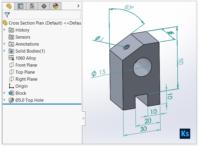
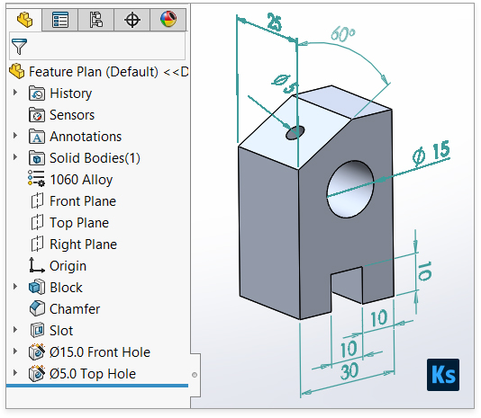
To highlight the difference we’re going to design a part with extrusions, two holes, a slot, and a chamfer in two ways. The first way sketches the overall shape and then adds the details in two steps (Cross Section Plan). The second way adds each detail one by one in five steps (Feature Plan). Both ways make the same part, but the second way is easier to change later. Remember, the goal is to maintain design intent for ease of future modifications and to design the part as if it were being manufactured.
Cross Section Plan:
- Sketch the Cross Section:
- Open a new part in SolidWorks.
- Select a plane to sketch on (e.g., Front Plane).
- Use the Line tool to sketch the outline of the slider block’s cross-section, including the outline of the slot.
- Use the Smart Dimension tool to define the size and positions accurately, as per the design requirements.
- Extrude the Sketch:
- Select the Extruded Boss/Base feature.
- Choose the sketch of the cross-section.
- Set the depth of the extrusion to match the length of the slider block.
- Confirm to create the solid extrusion.
- Add Holes and Chamfer:
- Use the Hole Wizard or the Extruded Cut feature to create the two holes at their specified locations.
- Select the edges where the chamfer is required and apply the Chamfer feature, specifying the desired size.
Features Plan:
- Create the Base Extrusion:
- Start with a new part and select a plane for the base sketch.
- Sketch a rectangle for the base of the slider block, without the slot.
- Use the Extruded Boss/Base feature to extrude the rectangle to the required thickness of the block.
- Cut the Slot:
- Select the face where the slot will be.
- Sketch the shape of the slot.
- Use the Extruded Cut feature to remove material, creating the slot through the block.
- Drill Holes:
- For each hole, select the surface where the hole will start.
- Use the Circle tool to define the hole’s position and diameter.
- Use the Extruded Cut feature again to drill each hole to the required depth.
- Add Fillets (if required):
- If the design requires rounded edges, use the Fillet feature.
- Select the edges to be filleted and specify the radius.
- Apply Chamfer:
- Select the Chamfer feature and then choose the edges where chamfers are needed.
- Specify the chamfer dimensions and apply.
Each plan has its merits, but as noted, the Features Plan might offer more flexibility for future modifications due to the stepwise approach that closely mimics the manufacturing process.
The Features Plan is generally considered better for modifications in SolidWorks for several reasons, all of which stem from its approach to building the part through a series of discrete, logically sequenced operations that mirror the manufacturing process. This method provides greater flexibility and control when changes are needed, for the following reasons:
- Parametric and Feature-Based Modeling: SolidWorks is a parametric and feature-based CAD software, meaning each operation (feature) you apply (such as extrusions, cuts, fillets, and chamfers) is stored in the part’s feature tree. This allows for easy modifications as you can edit individual features without affecting the entire model, which is particularly advantageous in the Features Plan where the part is built up through a series of distinct features.
- Ease of Editing: With each feature created independently, you can edit a single feature (like the size of a hole, the depth of a slot, or the dimensions of a chamfer) without needing to redo the entire model. This is particularly useful for iterative design processes where dimensions and shapes are frequently tweaked.
- Better Control Over Design Intent: Design intent refers to the idea that the CAD model should be constructed in a way that anticipates future changes. By using the Features Plan, the designer has more control over how modifications are implemented because each feature can be adjusted independently, preserving the overall design intent.
- Manufacturing Process Simulation: The Features Plan more closely simulates the manufacturing process, where a part is typically made by adding and removing material in a series of steps. This can be beneficial for designers and engineers who need to consider how the part will be made during the design phase, allowing for more manufacturing-friendly modifications.
- Dependency and Relations Management: In the Features Plan, relations and dependencies between features (like co-linear edges, equal diameters for holes, etc.) can be more easily managed and maintained through design changes. This ensures that modifications do not inadvertently compromise the part’s functionality or assembly compatibility.
- Feature Reordering: SolidWorks allows features to be reordered in the feature tree, which can be particularly useful if the design sequence needs to change due to modifications. This flexibility is inherent in the Features Plan approach, where the discrete nature of each feature allows for such reordering without significant rework.
The Features Plan offers a modular approach to design in SolidWorks, where each feature’s parameters can be individually adjusted or reconfigured, providing a more adaptable and resilient model for future changes.
Let’s consider a scenario where you have designed a slider block using the Features Plan in SolidWorks, and now you need to modify the design based on new requirements or feedback.
Original Design:
- The slider block has a base extrusion, a through slot in the centre, two drilled holes on either side of the slot, and a chamfer along the top edges.
Change Required:
- Due to a change in the assembly it fits into, the slot’s width needs to be increased, one hole’s diameter needs to be reduced, and the chamfer size needs to be increased for better stress distribution.
Advantages of the Features Plan for Making These Changes:
- Modifying the Slot Width:
- In the Features Plan, the slot is created using a separate “Extruded Cut” feature. To modify the width, you simply edit this feature, adjust the width dimension of the sketch defining the slot, and the change is applied. This isolated modification doesn’t affect the base extrusion or other features.
- Changing the Hole Diameter:
- Each hole is also created using its own “Extruded Cut” feature. To change the diameter of one hole, you would edit the sketch associated with that hole’s feature, adjust the diameter, and the software recalculates the cut without affecting the other hole or any other aspect of the part.
- Increasing the Chamfer Size:
- The chamfer is applied as a separate feature as well. To increase its size, you simply edit the chamfer feature, adjust the size parameters, and the change is made. This doesn’t require any alteration to the underlying geometry or other features.
Highlighting the Flexibility:
This scenario highlights the flexibility of the Features Plan due to the independence of each feature. In a Cross Section Plan, where the part might be created from a single sketch and extrusion, making such changes would require editing the original sketch. This could be more complex and time-consuming, especially if the sketch is intricate, and it might also inadvertently affect other dimensions or features due to sketch relations and constraints.
In contrast, the Features Plan’s modular approach allows for targeted modifications with minimal risk of unintended consequences on the rest of the part, demonstrating its superiority for ease of modification and adaptability to design changes.
To sum up, the Features Plan in SolidWorks lets you change each part’s details on its own, making your design more flexible and easier to update later. Basically, your design goals shape the plan, and the way the design works makes it happen. A project engineer has to consider both the design’s aims and how it will be used, making sure the welding fixture meets both the users’ needs and practical engineering standards. Finding this balance is key to making a product that’s not only creative and easy to use but also strong, dependable, and works well where it’s supposed to.