SolidWorks in the Structural Design and Optimisation of Aerial Work Platforms (AWP)
Designing lifting equipment for industrial use is a critical task that demands attention to detail, robust engineering principles, and a deep understanding of the operational environment. This equipment plays a vital role in various sectors, including construction, manufacturing, and logistics, by facilitating the safe and efficient handling of heavy materials.
Understanding Requirements
The first step in designing lifting equipment is to understand the specific requirements of the task thoroughly. This includes the weight and dimensions of the materials to be lifted, the frequency of lifting operations, and the environmental conditions in which the equipment will operate. For instance, equipment designed for outdoor use in a shipyard will differ significantly from that intended for indoor use in a manufacturing plant.
Safety First
Safety is paramount in the design of lifting equipment. The equipment must comply with stringent safety standards and regulations to protect operators and bystanders. This involves incorporating safety features such as load limiters, which prevent the equipment from lifting beyond its capacity, and fail-safe mechanisms that engage in the event of a power failure or mechanical breakdown.
In the UK, the design and use of Mobile Elevating Work Platforms (MEWPs) are regulated by the Health and Safety Executive (HSE). The key regulations include the Provision and Use of Work Equipment Regulations 1998 (PUWER) and the Lifting Operations and Lifting Equipment Regulations 1998 (LOLER). These regulations mandate that MEWPs must be fit for purpose, regularly inspected, and maintained, and used by trained operators.
Additionally, British Standard BS EN 280 outlines specific design calculations, stability criteria, and safety requirements for MEWPs. Adhering to these standards is crucial for ensuring the safety and reliability of the platforms.
Material Selection
The choice of materials is crucial in the construction of lifting equipment. The materials must possess the necessary strength to handle the expected loads while being as lightweight as possible to ensure efficiency and ease of operation. High-strength steel alloys are commonly used due to their excellent strength-to-weight ratio.
Mechanical Design
The mechanical design of lifting equipment involves detailed calculations to ensure that all components, including beams, cables, and pulleys, can withstand the forces exerted during lifting operations. Finite Element Analysis (FEA) software, such as SolidWorks, is often used to simulate and analyse the stresses and strains on the equipment, allowing for optimisation of the design for both performance and safety.
Ergonomics and Usability
Ergonomics play a significant role in the design of lifting equipment. The controls and interfaces should be intuitive and easily accessible, reducing operator fatigue and the risk of errors. Adjustable features like telescopic booms or variable-speed controls can enhance usability and adaptability to different tasks.
Maintenance and Reliability
Reliability is essential for lifting equipment, as downtime can significantly impact operational efficiency. The design should facilitate easy access for maintenance and repairs, with components that are durable and readily available. Regular maintenance schedules and thorough inspections are critical to ensuring the long-term reliability of the equipment.
Innovation and Technology
The integration of technology, such as automation and remote control, is increasingly common in lifting equipment design. These advancements can improve precision, efficiency, and safety, allowing for complex lifting operations to be performed with minimal human intervention.
Designing lifting equipment for industrial use is a complex task that requires a holistic approach, encompassing safety, functionality, and efficiency. By adhering to established engineering principles, leveraging advanced design software, and incorporating innovative technologies, engineers can develop lifting solutions that meet the demanding requirements of modern industry, ensuring safe, efficient, and reliable operations.
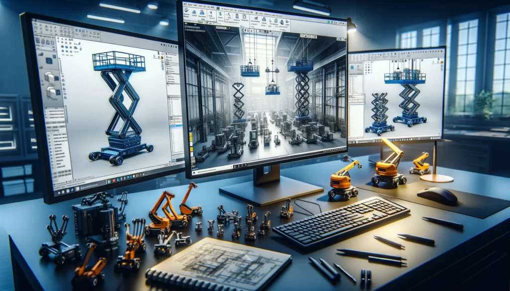
When delving into the mechanical design aspect of lifting equipment using SolidWorks, a practical example can illustrate the process effectively. Consider the design of an overhead crane beam, a common type of lifting equipment used in warehouses and manufacturing plants.
Step 1: Conceptualisation and Requirements Definition
The design process begins with defining the specific requirements for the crane beam, such as its maximum lifting capacity, which might be 10 tonnes, and the span, which could be 15 meters to cover the required operational area. At this stage, considerations regarding the operational environment, such as indoor use with minimal exposure to corrosive substances, are also taken into account.
Step 2: Initial Sketches and SolidWorks Modelling
Using SolidWorks, the designer starts by creating a 2D sketch of the crane beam profile. This might involve a simple I-beam or a box girder section, depending on the load and span requirements. The sketch includes the main dimensions, such as the height and width of the beam, and the thickness of the flanges and web.
Step 3: 3D Modelling and Material Selection
The 2D sketch is then extruded to create a 3D model of the crane beam. The material for the beam is selected based on the strength and weight requirements, with a common choice being a high-strength steel alloy, such as ASTM A992. The material properties, including density, yield strength, and modulus of elasticity, are input into SolidWorks to accurately simulate the behaviour of the beam under load.
Step 4: Finite Element Analysis (FEA)
With the 3D model complete, the designer uses SolidWorks Simulation, an FEA tool, to analyse the beam’s performance. The load conditions, representing the maximum lifting capacity, are applied to the model, along with constraints that mimic the real-world support conditions of the beam. The FEA tool calculates the stress distribution, deformation, and factor of safety for the beam. Areas of high stress are identified, indicating where the design might need reinforcement or alteration.
Step 5: Optimisation
Based on the FEA results, the designer optimises the crane beam design. This might involve increasing the thickness of the flanges or web in high-stress areas or altering the beam’s profile to improve its load-carrying capacity. The goal is to achieve a structurally sound design and as lightweight as possible to enhance efficiency and reduce material costs.
Step 6: Detailing and Fabrication Drawings
Once the optimised design is finalised, detailed drawings are created within SolidWorks. These drawings include all critical dimensions, tolerances, and specifications required for fabrication. Welding symbols, material specifications, and surface finish requirements are also included to guide the manufacturing process.
Step 7: Assembly and Integration
If the crane beam is part of a larger assembly, such as an overhead crane with a trolley and hoist, the designer uses SolidWorks to model the entire assembly. This ensures that all components fit together correctly and that the beam integrates seamlessly with the rest of the crane components.
This illustrates how SolidWorks is utilised in the mechanical design of lifting equipment, from initial concept through to detailed fabrication drawings. The software’s powerful modelling and simulation capabilities enable designers to create efficient, reliable, and safe lifting solutions tailored to the specific requirements of the industrial application.
The engineering theory behind the design of lifting equipment encompasses several key principles and calculations. These ensure that the equipment is not only capable of performing its intended function but does so safely and efficiently. The example of designing an overhead crane beam, as discussed previously, involves a variety of engineering theories, including statics, dynamics, material science, and structural analysis.
Statics and Load Analysis
The fundamental theory of statics is crucial in understanding how forces are distributed within a structure. For an overhead crane beam, the primary concern is how it bears the loads applied to it, including the weight of the lifted object, the weight of the crane components (trolley, hoist), and the self-weight of the beam. The analysis involves calculating the reactions at the supports and the internal forces (shear force and bending moment) along the length of the beam.
- Shear Force and Bending Moment Diagrams: These are graphical representations that show how internal shear forces and bending moments vary along the length of the beam. They are essential for identifying points of maximum stress.
Dynamics
Although the primary analysis is static, understanding the dynamics involved, especially during the lifting or lowering of loads, is important. This includes the effects of acceleration and deceleration of the crane trolley and the dynamic loading that can occur when a load is suddenly dropped or stopped.
- Impact Factor: This accounts for the additional forces exerted due to the dynamic effects, which can significantly increase the stress in the crane beam compared to static loading alone.
Material Science
The selection of materials is based on their mechanical properties, such as yield strength, ultimate strength, elasticity, and toughness. High-strength steel alloys are often chosen for their favourable strength-to-weight ratios and durability.
- Factor of Safety (FoS): This is a design criterion that ensures the beam has sufficient strength beyond the expected maximum load. It is the ratio of the material’s yield strength to the maximum stress experienced in the beam under load.
Structural Analysis
Structural analysis involves determining the stress distribution within the beam to ensure it remains within safe limits under all expected load conditions.
- Stress Analysis: Using the bending moment and shear force, the stress at any point in the beam can be calculated. The maximum bending stress in a beam is given by the formula σ=M⋅yIσ=IM⋅y, where MM is the bending moment, yy is the distance from the neutral axis, and II is the moment of inertia of the beam’s cross-section.
- Deflection Analysis: It’s also critical to ensure that the beam’s deflection under load does not exceed allowable limits, which could impact the crane’s operation. The deflection is influenced by the beam’s material (modulus of elasticity) and geometry (moment of inertia).
Finite Element Analysis (FEA)
FEA is a computational tool that simulates the physical behaviour of the crane beam under various load conditions. It divides the beam into small elements and solves the stress, strain, and displacement for each under the applied loads. This method allows for a detailed analysis of complex structures where analytical solutions are not feasible.
The design of lifting equipment like an overhead crane beam involves a comprehensive application of engineering theories. From ensuring structural integrity through static and dynamic load analysis to optimising the material selection for durability and efficiency, each step is governed by fundamental engineering principles. These theories, combined with practical considerations and safety standards, guide engineers in developing lifting solutions that meet the rigorous demands of industrial applications.
SolidWorks offers a suite of tools that significantly aid in applying engineering theory to the design of lifting equipment, such as overhead crane beams. The software’s capabilities span from initial design and 3D modelling to advanced simulations, allowing engineers to apply theoretical principles effectively throughout the design process.
Application of Statics and Load Analysis
- Sketch Tools and Structural Members: SolidWorks allows for the creation of precise 2D sketches that can be used to define the geometry of crane beams. The software’s structural member tool can then extrude these sketches into 3D models, providing a visual and dimensional representation of the beam.
- Force and Load Applications: Engineers can apply forces and loads directly to the model in SolidWorks, simulating real-world conditions such as the weight of the load, the self-weight of the beam, and additional forces due to the movement of the crane.
Dynamics and Motion Analysis
- SolidWorks Motion: This module enables the simulation of the crane’s moving parts, such as the trolley and hoist. Engineers can analyse the dynamic effects on the crane beam, including the impact of acceleration, deceleration, and sudden stops, which helps in understanding how these factors influence the design.
Material Selection and Analysis
- Material Properties Database: SolidWorks includes a comprehensive database of material properties, allowing engineers to select the appropriate material for the crane beam based on its mechanical properties such as yield strength, density, and elasticity.
- Simulation Studies: By assigning selected materials to the model, engineers can conduct simulation studies to observe how the material choice affects the beam’s performance under load, ensuring the selected material meets the design requirements.
Structural Analysis and FEA
- SolidWorks Simulation: This powerful tool performs finite element analysis (FEA) on the crane beam model, breaking it down into finite elements and calculating the stress, strain, and displacement for each element under applied loads.
- Stress Analysis: SolidWorks Simulation provides detailed visualisations of stress distributions across the beam, highlighting areas of high stress that may require reinforcement or design modification.
- Deflection Analysis: The software also calculates and visualises the deflection of the crane beam under load, ensuring that it remains within acceptable limits to maintain operational integrity and safety.
Design Optimisation
- Design Study: SolidWorks offers a design study environment where engineers can explore various design scenarios, adjusting dimensions, shapes, and materials to optimise the crane beam for weight, strength, and cost.
- Parametric Modeling: Changes to the model parameters automatically update the entire model, allowing for rapid iterations and optimisations based on simulation results.
Documentation and Compliance
- Detailed Drawings: SolidWorks enables the creation of detailed fabrication drawings directly from the 3D model, including dimensions, tolerances, and annotations, which are essential for manufacturing and compliance with industry standards.
- Simulation Reports: Engineers can generate comprehensive reports from simulation studies, providing valuable documentation for design validation, compliance with safety standards, and communication with stakeholders.
Conclusion
SolidWorks bridges the gap between theoretical engineering principles and practical application in the design of lifting equipment. By offering tools for detailed modelling, simulation, and optimisation, SolidWorks empowers engineers to create safe, efficient, and reliable lifting solutions, grounded in sound engineering theory and optimised through advanced computational analyses.