Design Principles and Practices to Reduce Pressure Drop and Enhance System Efficiency
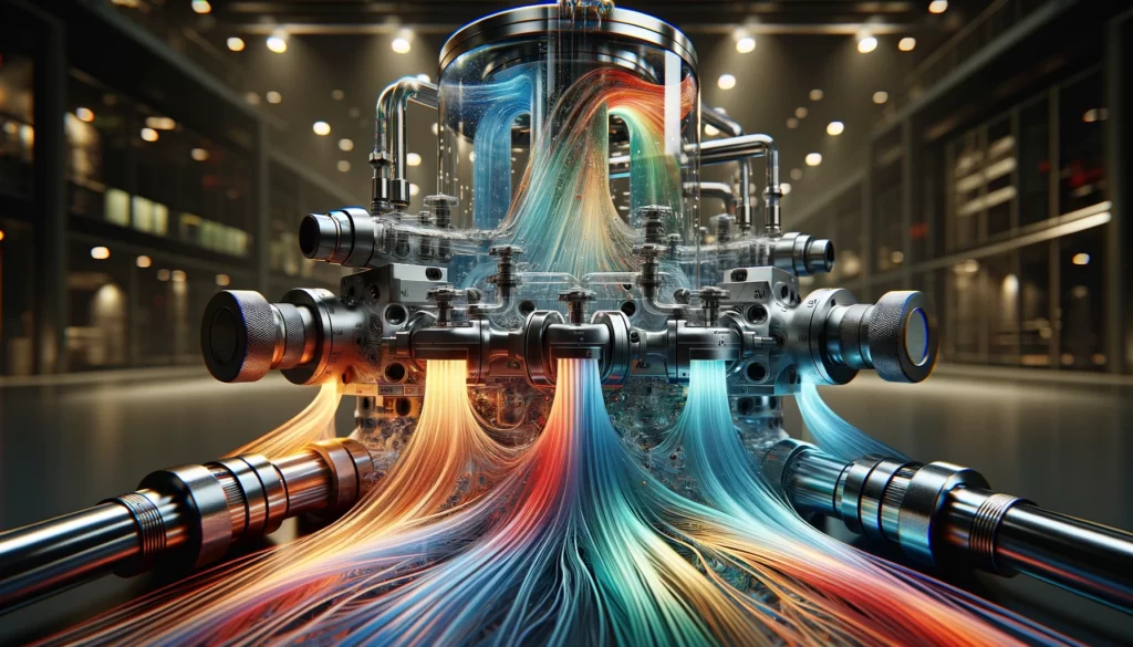
Hydraulic manifolds are integral components in hydraulic systems, serving as central hubs through which hydraulic fluid flows to various parts of the system. These compact, block-like structures route the fluid between the pump, actuators, valves, and other hydraulic equipment, playing a critical role in controlling the movement and operation of the machinery.
Structure and Functionality:
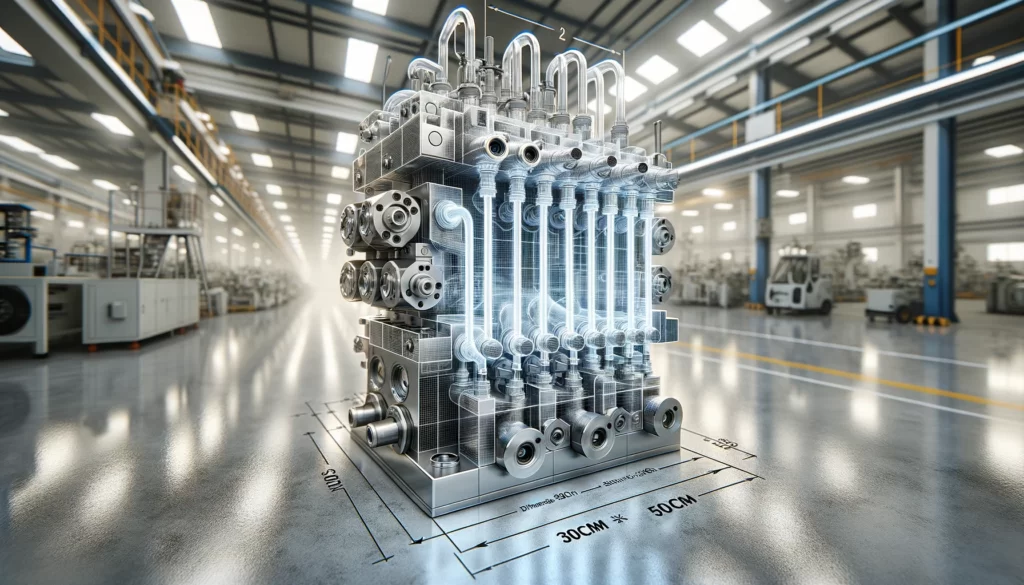
- Design: Typically made from durable materials like steel or aluminium, manifolds consist of a series of channels and ports machined within a solid block. These internal passages direct hydraulic fluid to and from different components, based on the manifold’s design.
- Ports: The manifold includes various inlet and outlet ports that connect to hydraulic pumps, valves, cylinders, and other system components. These ports are strategically positioned to optimise fluid flow paths and reduce the system’s complexity and footprint.
- Valve Integration: Manifolds often incorporate cavities designed to house hydraulic valves directly. This integration allows for streamlined control over fluid direction, pressure, and flow rate within the system.
Reasons for Using Manifolds in Hydraulic Systems:
- Space Efficiency:
- Manifolds consolidate multiple components into a single, compact unit, reducing the need for extensive piping and hose connections. This minimises the system’s overall size, making it more manageable and easier to incorporate into machinery.
- Reduced Leak Points:
- By diminishing the number of connections required between components, manifolds significantly lower the potential for leaks. This enhances system reliability and reduces maintenance requirements.
- Improved Performance:
- The careful design of a manifold’s internal passages can optimise fluid flow, reducing pressure drops and turbulence. This leads to more efficient system operation and can enhance the performance of the connected machinery.
- Customisation and Flexibility:
- Manifolds can be custom-designed to meet the specific needs of an application, allowing for tailored fluid routing and control. This customisation capability makes them suitable for a wide range of systems, from simple to highly complex configurations.
- Simplified Maintenance:
- With fewer external connections and the centralisation of components, manifolds simplify system maintenance. Troubleshooting and repairs can be more straightforward, with easier access to valves and passages within the manifold.
- Cost-Effectiveness:
- Although the initial cost of a custom manifold can be higher than using discrete components, the overall cost savings from reduced assembly time, lower maintenance costs, and improved system reliability often justify the investment.
Hydraulic manifolds are essential for the efficient, reliable, and compact design of hydraulic systems. They facilitate precise control over fluid flow, minimise potential leak points, and can be customised to meet the unique demands of various applications, making them indispensable in modern hydraulic machinery.
Minimising pressure drop in a hydraulic manifold involves careful design and maintenance practices to ensure efficient flow paths and reduce restrictions. Here are some strategies to achieve this:
- Optimise Internal Passages:
- Design the internal channels of the manifold to be as straight and short as possible, reducing turns and bends that can cause turbulence and increase resistance.
- Use gradual changes in direction to minimise turbulence and the associated pressure drops.
- Correct Sizing:
- Ensure the ports and internal passages are appropriately sized for the flow rate. Oversized passages can reduce pressure drop but may lead to slower system response, while undersized passages can create excessive pressure drops.
- Calculate the optimal size based on the system’s flow rate and the specific application requirements.
- Surface Finish:
- Maintain a smooth surface finish inside the manifold channels. Rough surfaces increase friction and turbulence, leading to higher pressure drops.
- Component Placement:
- Place components in a way that minimises sharp bends in the fluid’s flow path. Strategic placement can reduce the length of the flow paths and minimise pressure losses.
- Use of Accumulators:
- Install accumulators close to the manifold to help maintain pressure levels in the system, especially during peak demand periods. This can help in smoothing out the flow and reducing pressure fluctuations.
- Regular Maintenance:
- Perform regular maintenance to prevent clogging and contamination, which can significantly increase pressure drop. This includes cleaning filters and checking for any obstructions in the flow paths.
- Minimise Leakages:
- Ensure all connections and components are well-sealed to prevent leaks. Leakage can lead to a significant drop in system pressure.
- Simulation and Testing:
- Use computational fluid dynamics (CFD) simulations during the design phase to predict how fluids will flow through the manifold and identify potential high-pressure drop areas.
- Conduct physical testing under various operating conditions to validate the design and make necessary adjustments.
By implementing these strategies, you can effectively minimise pressure drops in a hydraulic manifold, leading to a more efficient and reliable hydraulic system.

The theory behind minimising pressure drop in hydraulic manifolds involves understanding fluid dynamics and the factors that influence the resistance to fluid flow within the system. Key principles include:
- Bernoulli’s Principle:
- This principle states that an increase in the speed of a fluid occurs simultaneously with a decrease in pressure or a decrease in the fluid’s potential energy. In the context of hydraulic manifolds, it’s essential to balance the flow velocity and pressure to minimise energy losses.
- Reynolds Number:
- The Reynolds number is a dimensionless quantity that helps predict flow patterns in different fluid flow situations. Laminar flow (low Reynolds number) is characterised by smooth, constant fluid motion, while turbulent flow (high Reynolds number) is characterised by chaotic changes in pressure and flow velocity. Laminar flow is generally more desirable in hydraulic systems as it leads to lower pressure drops.
- Darcy-Weisbach Equation:
- This equation is used to calculate the pressure drop due to friction in a pipe or channel:
\(\Delta P = f \cdot \left(\frac{L}{D}\right) \cdot \frac{\rho v^2}{2}\) where ΔP is the pressure drop, f is the Darcy friction factor, L is the length of the pipe, D is the diameter of the pipe, ρ is the fluid density, and v is the flow velocity. In manifold design, minimising the length L and optimising the diameter D are key to reducing pressure drop.
- This equation is used to calculate the pressure drop due to friction in a pipe or channel:
- Continuity Equation:
- The principle of conservation of mass for fluid flow, states that the mass flow rate in a conduit must remain constant. It implies that any change in the cross-sectional area through which the fluid flows will result in a change in the flow velocity. This is critical when designing the internal passages of a manifold to ensure a consistent flow rate while minimising pressure drop.
- Viscosity and Fluid Properties:
- The viscosity of the hydraulic fluid plays a significant role in determining the resistance to flow. Higher-viscosity fluids tend to have higher friction losses, leading to greater pressure drops. The selection of hydraulic fluid should consider the operating temperature and the system’s requirements to ensure optimal viscosity.
- Hagen-Poiseuille Equation:
- For laminar flow, the Hagen-Poiseuille equation can be used to calculate the pressure drop in a circular pipe:
\(\Delta P = \frac{8 \mu L Q}{\pi r^4} \) where ΔP is the pressure drop, μ is the dynamic viscosity of the fluid, L is the length of the pipe, Q is the volumetric flow rate, and r is the radius of the pipe. This equation highlights the importance of the radius (or diameter) of the passages in controlling pressure drop.
- For laminar flow, the Hagen-Poiseuille equation can be used to calculate the pressure drop in a circular pipe:
Understanding and applying these principles in the design and operation of hydraulic manifolds are crucial for minimising pressure drop, ensuring efficiency, and maintaining the desired performance of the hydraulic system.
SolidWorks, a prominent computer-aided design (CAD) and engineering software offers extensive tools and features that can greatly assist in the design, analysis, and optimisation of hydraulic manifolds to minimise pressure drop. Here’s an example of how SolidWorks can be used in this process:
Step 1: Design and Modeling
- Initial Design: Utilise SolidWorks to create a detailed 3D model of the hydraulic manifold, including all internal passages, ports, and mounting features. The software’s intuitive design tools allow for the easy manipulation of geometry to optimise flow paths.
- Parameterisation: With SolidWorks, parameters such as the diameter and length of channels, the radius of curves, and the position of ports can be easily adjusted. This allows for rapid iterations in the design to explore different configurations.
Step 2: Flow Simulation
- CFD Analysis: SolidWorks Flow Simulation is a Computational Fluid Dynamics (CFD) tool that integrates seamlessly with the CAD environment. It allows for the simulation of fluid flow within the manifold, providing insights into velocity, pressure distribution, and potential areas of high turbulence or restriction.
- Parameter Studies: Conduct parametric studies to see how changes in design variables affect the pressure drop. This can include varying the size and shape of passages, the smoothness of internal surfaces, or the layout of the manifold.
Step 3: Optimisation
- Design Optimisation: Use SolidWorks to apply optimisation techniques where the software automatically adjusts design parameters within specified ranges to minimise the pressure drop while maintaining other design constraints.
- Goal Seeking: SolidWorks can perform goal-seeking analyses to find the best configuration that meets specific performance targets, such as minimising pressure drop or balancing flow distribution across different branches of the manifold.
- Real-World Data Incorporation: After testing, real-world performance data can be fed back into SolidWorks to further refine the design, ensuring that the final product performs as intended.
Example Scenario:
Imagine designing a hydraulic manifold that needs to distribute fluid evenly to multiple actuators with minimal pressure loss. Using SolidWorks, you start by modelling the manifold with several design iterations, focusing on streamlining the flow paths and optimising the port placement. You then run CFD simulations to identify areas where fluid velocity is too high, indicating potential pressure drops. Adjustments are made to the model based on simulation feedback, such as widening certain passages and adding fillets to reduce turbulence. After a few iterations, you identify a design that meets the desired criteria.
By leveraging SolidWorks’ comprehensive suite of design, simulation, and prototyping tools, engineers can significantly improve the efficiency and performance of hydraulic manifolds, reducing pressure drops and enhancing system reliability.